
General Information
| Name in local language: | Pont de Normandie |
|---|---|
| Beginning of works: | 1989 |
| Completion: | 20 January 1995 |
| Status: | in use |
Project Type
| Structure: |
Cable-stayed bridge with semi-fan system |
|---|---|
| Function / usage: |
Motorway bridge / freeway bridge |
| Material: |
Steel-concrete hybrid bridge |
| Structure: |
Three-span cable-stayed bridge |
| Support conditions: |
for registered users |
| Plan view: |
Structurae Plus/Pro - Subscribe Now! |
| Material: |
Structurae Plus/Pro - Subscribe Now! |
| Secondary structure(s): |
Structurae Plus/Pro - Subscribe Now! |
| Material: |
Structurae Plus/Pro - Subscribe Now! |
| Secondary structure(s): |
Structurae Plus/Pro - Subscribe Now! |
Awards and Distinctions
| 1998 |
award winner
for registered users |
|---|
Location
| Location: |
Le Havre, Seine-Maritime (76), Normandy, France Honfleur, Calvados (14), Normandy, France |
|---|---|
| Crosses: |
|
| Part of: | |
| Near: |
Passerelle de l'aire de la Baie de Seine (1995)
Pont de Normandie Toll Gate (1995) |
| Connects to: |
Grand Canal Bridge at Le Havre (1994)
|
| Coordinates: | 49° 26' 35.16" N 0° 16' 21.27" E |
| Coordinates: | 49° 25' 14.27" N 0° 16' 31.85" E |
Technical Information
Dimensions
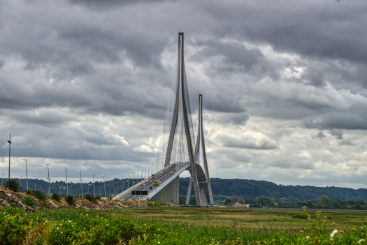
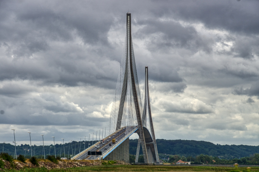
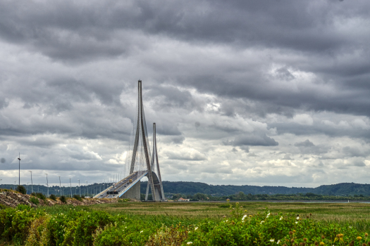
| main span | 856.00 m | |
| total length | 2141 m | |
| deck | deck width | 21.20 - 22.30 m |
| girder depth | 3.00 m | |
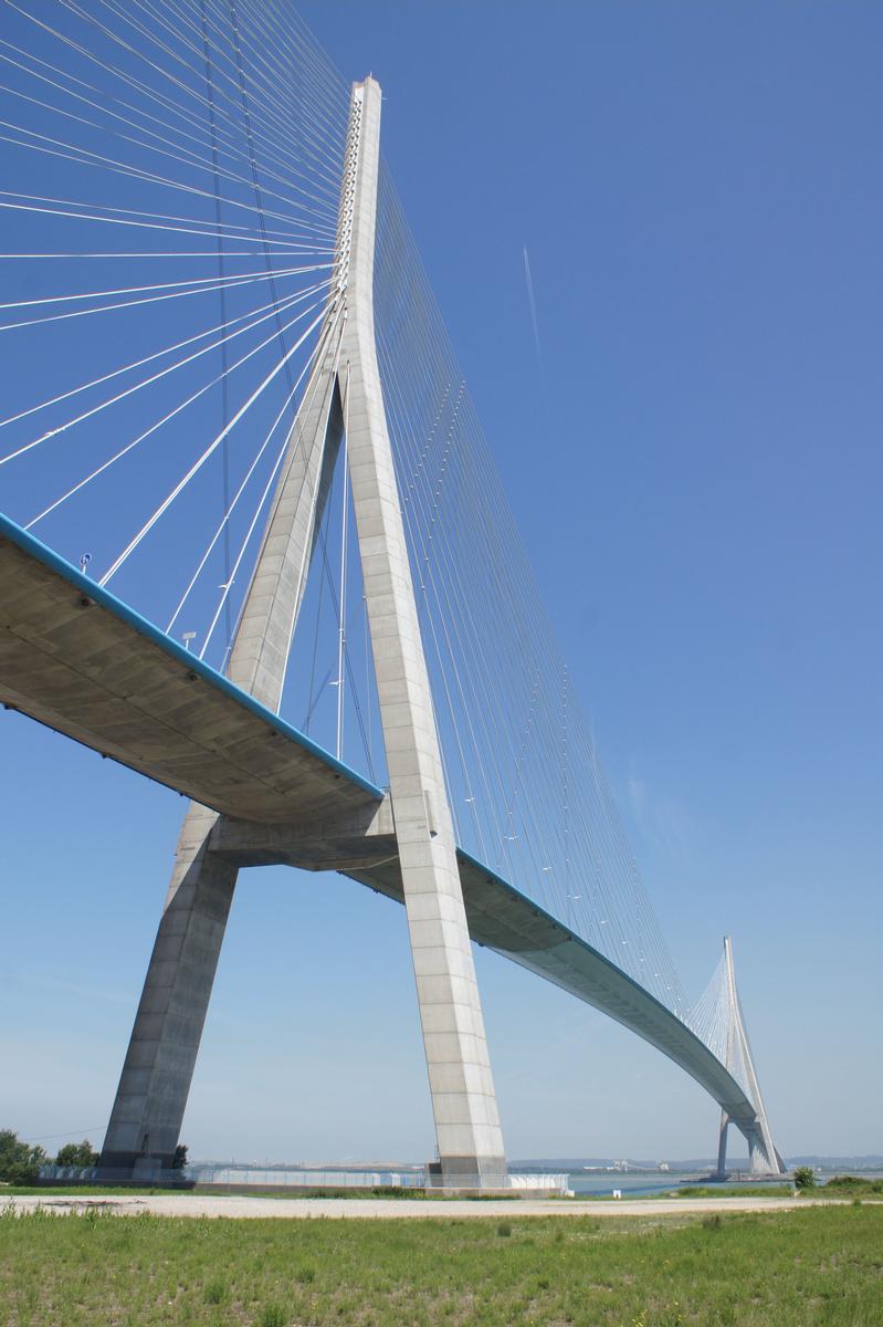
| pylon | total height | 214.77 m |
| pylon height (above deck) | 155.70 m |
Quantities
| structural steel | 5 700 t | |
| concrete volume | 80 000 m³ | |
| prestressing steel | 800 t | |
| reinforcing steel | 11 600 t | |
| steel for cable-stays | 2 000 t | |
| paint | 16 600 m² |
Materials
| approach viaducts |
prestressed concrete
|
|---|---|
| pylons |
reinforced concrete
|
| central section of main span |
steel
|
| ends of main span |
prestressed concrete
|
Case Studies and Applied Products
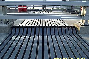
TENSA®MODULAR LR & LR-LS – Modular expansion joints
Modular Expansion Joints can be constructed for any movements, from about 100 mm up to 2,000 mm and more. They allow movements in all 3 directions and rotations around all 3 axes.
[more]Chronology
| September 1990 — 1992 | Construction of foundations. |
|---|---|
|
August 1991
— August 1993 |
Construction of access ramps. |
|
September 1991
— August 1993 |
Construction of the pylons. |
|
January 1992
— August 1994 |
Assembly of the metal section of the bridge's main deck. |
|
October 1992
— October 1993 |
Construction of the prestressed concrete deck section of the main bridge by cantilever construction. |
Notes
Part of the deck cantilevering out from the pylons was built as a hollow box made of prestressed concrete, but about two thirds of the deck are made of a steel.
Due to the earth's curvature and the great length of the bridge, the distance between the pylons is 2 cm greater at the top than at the base.
Design considerations
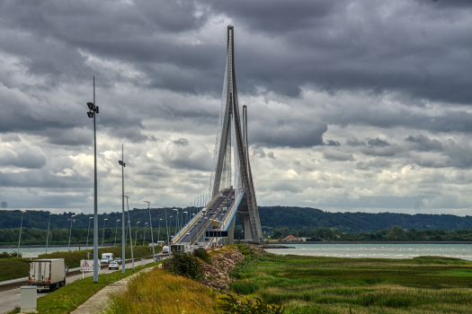
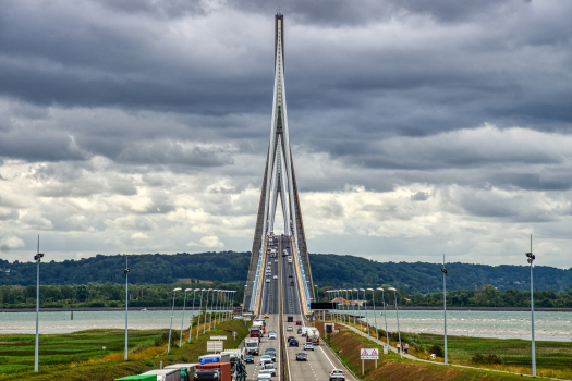
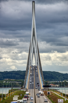
The Normandy Bridge was completed on 8 August 1994. Its main span length of 856 m made it by far the largest cable-stayed bridge of the world. Three precursors in Germany with one only tower had previously indicated that such spans were possible: The Severins Bridge in Cologne with 302 m main span in 1959, the Knie Bridge with 320 m main span in 1969 and the Flehe Bridge with 368 m main span in 1979. During the design period of the Normandy Bridge (originally called Honfleur Bridge) the span record for bridges with two towers was twice exceeded: In November 1991 by the Skarnsundet Bridge in Norway with a main span of 530 m and by the Yang Pu Bridge in Shanghai in 1993 with a main span of 602 m. (The current record holder is the Sutong Bridge in China with 1088 m from 2008.) The governing design assumptions for the Normandy Bridge are:
- streamlined cross-sections for main and side spans in order to reduce the wind loads and to improve the aerodynamic stability
- closed box girder cross-sections in order to achieve a high torsional stiffness, which, together with A-shaped towers, increases the torsional frequency and thus the aerodynamic stability
- A-towers also for achieving a high transverse stiffness
- a light steel girder in the main span and heavy concrete girders in the side spans as counterweights (for this combination of steel main span and concrete side spans, the author uses the designation „hybrid bridge“)
- the concrete side span beams protruding 116 m into the main span for improved stiffness and economy
- use of high-strength concrete B 60
- –composite anchorage of the parallel strand cables in the tower heads
- special provisions for improving the aerodynamic stability of the stay cables which are sensitive because of the large span and the light steel cross-section.
Structural design
The complete bridge beam – approaches, side spans and main span – has a similar box girder cross-section with a depth of 3 m (slenderness = 3:624 = 1:208) and inclined outer bottom slabs. The 203 m high concrete A-towers also have box girder cross-sections. The stay cables are anchored at the upper part of the tower in composite boxes. The horizontal tensile forces between forestays and backstays are directly connected by the longitudinal steel plates. The vertical cable components are introduced into the tower legs via the vertical steel plates. The 8 × 23 = 184 parallel strand stay cables use monostrands. They are anchored with wedges in retainer plates at the ends of the anchor heads.
Cable dynamics
Since the longest cables have a record length and because the steel beam in the main span is rather light, several provisions were selected to stabilize the cables against oscillations. First provision: In order to prevent rain–wind-induced cable oscillations the PE pipes were provided with outer helical fillets, which prevent the formation of upper and lower rivulets that can cause substantial cable oscillations due to galloping. Second provision: Between the stay cables ties were installed, which increase the eigenfrequency of the stay cables by providing additional elastic supports. In this way their sensitivity against parametric and anchorage excitation is strongly reduced. Third provision: Near the cable anchorages at the beam hydraulic dampers are installed which dampen all types of cable oscillations. The driver’s view along the bridge shows clearly the tie-downs and the hydraulic dampers. The appearance of the bridge is in this way slightly impaired.
Construction
Tower
Load-bearing limestone is found in 40 m depth only. All foundations thus rest on concrete piles with 1.5 to 2.1 m diameter and lengths of up to 55 m. Underneath the north approach a 4 m thick layer of silt is located which required the construction of a temporary construction bridge from which all foundation works were executed. The pile caps are 3.5 m deep, transversely post-tensioned and highly reinforced. The tower legs are monolithic with the pile caps. They were built by free cantilevering with sliding forms. Up to the cross girders underneath the deck the bending from transverse inclination did not require lateral supports. Between deck level and the point where the two tower legs meet one temporary steel truss strut was required. The steel elements for the cable anchorage in the tower top were shop-fabricated and transported to the site. They were lifted into their final position with the tower crane. Finally the steel anchor boxes were surrounded with concrete in order to achieve the desired composite action for bending and transfer of the vertical cable components into the tower legs.
Concrete approach bridges
After casting of the towers, the outer approaches were built by incremental launching. The last part of each side span which protrudes into the main span was built by free-cantilevering to both sides of the towers outwards. Then followed the free-cantilevering of the remaining steel main span. The seagoing vessels on the Seine River required a navigational clearance of 56 m. In order to keep the lengths of the approach bridges to a minimum, they are given the maximum possible slope of 6 %. This steep grade required a modification of the standard incremental launching method which would have resulted in too large horizontal forces of 30 MN at the abutments and high friction forces at the pier heads. The so-called „lift-launch method“ was used which separates every inclined launching increment of the deck into its 150 mm horizontal and 9 mm vertical movements. Thereby each concrete box girder is launched on wedges which slide across the pier heads. The undersides of the wedges are horizontal, their inclined surfaces have the bridge slope of 6 %. The box girder is shifted alternately 150 mm horizontally with jacks located at the abutments and lifted by 9 mm with jacks located on each pier head outside of the wedges. Special sensors for the control of the horizontal and vertical movements were located at each pier head. Their results were combined in a central computer which controlled every single movement. It was especially important that the vertical movements were synchronized. The final part of the concrete beam at both sides of the towers was built by free-cantilevering. The 116 m long part protruding into the main span was built in 42 sections, the backwards parts in 31 sections. The concrete was placed alternately in the river and shore side in order to keep the cantilevers in balance. Each new section was supported by temporary stays. After every five sections supported by temporary stays a final stay cable was installed into the sixth section and the temporary stays were removed for reuse. In a general investigation the author has shown that for major steel main spans it is advantageous to build the outside parts in concrete with lengths in the range of 120 m, independent of the main span length. In this region it is economical to carry the high compression forces by concrete, and the stiffer concrete beam increases the eigenfrequencies of the main span, thereby improving its aerodynamic stability. The cost advantage has to be compared with the additional costs required for another construction method, in this case free cantilevering in addition to incremental launching. As a consequence, the protruding concrete cantilever in many cases is only extended as far as the original construction method for the approach beams permit. For the Normandy bridge that would be about 45 m, but at least one auxiliary pier to cross the last side span with 96 m would have been required additionally on each side. The most economic solution has thus to be carefully investigated for every bridge.
Steel main span
The 624 m long steel beam of the main span comprises 32 sections with lengths of 19.65 m. In order to save time the fabrication took place in two different shops. After successful pre-assembly, the sections were transported to the bridge on barges. The elements were lifted with erection derricks located at the beam tips. The beam was strong enough and the elements light enough so that no tie-backs were required for the derricks. During installation of the final sections a dynamic tuned mass damper (TMD) with a total mass of 50 t was installed at both cantilever tips to reduce the transverse oscillations due to strong wind.
Cable installation
Modern parallel strand cables are fabricated on site from their individual components, thereby avoiding the transportation of heavy shop-fabricated cables whose weights and reel diameters increase with the cable length. The monostrands are delivered to the site on specially built reels with brakes. The strands are pulled up inside the PE pipe to the tower head with the help of a to and fro running shuttle element. For stressing, the strands protrude well beyond the anchor plates. Since each strand is stressed individually only small monojacks are required. This is an additional advantage against shop-fabricated cables which have to be stressed as a unit with several-ton heavy hydraulic jacks. By means of the so-called isotensioning method (Freyssinet) all strands receive the same force. The first pilot strand of each cable is stressed to a precalculated value which is continuously controlled by a load cell. Each newly installed strand is stressed to that level which the pilot strand has at that moment. In the end all individual strands and thus the complete cable have their theoretical force, independent of temperature conditions and random erection loads. The PE pipes of the Normandy bridge consist of two half-shells which are connected by a snap-in tongue-and-groove joints. Finally the tie-down cables were installed using abseiling techniques.
Completed bridge
The completed bridge looks slender and elegant. Seen against the setting sun the bridge appears very fragile, the cables giving the impression of a veil.
Excerpt from: Svensson, Holger Cable-Stayed Bridges, Wilhelm Ernst & Sohn Verlag für Architektur und technische Wissenschaften GmbH, Berlin (Germany), ISBN 343302992X; pp. 402-410. References to figures and literature were omitted.
Excerpt from Wikipedia
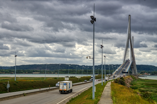
The Pont de Normandie (English: Normandy Bridge) is a cable-stayed road bridge that spans the river Seine linking Le Havre to Honfleur in Normandy, northern France. Its total length is 2,143.21 metres (7,032 ft) – 856 metres (2,808 ft) between the two piers. It is also the last bridge to cross the Seine before it empties into the ocean. Despite being a motorway toll bridge, there is a footpath as well as a narrow cycle lane in each direction allowing pedestrians and cyclists to cross the bridge free of charge.
Construction
The bridge was designed by Michel Virlogeux, the general studies have been led by Bernard Raspaud from Bouygues, and the works management was shared between G. Barlet and P. Jacquet. The architects were François Doyelle and Charles Lavigne. Construction by Bouygues, Campenon Bernard, Dumez, Monberg & Thorsen, Quillery, Sogea and Spie Batignolles began in 1988 and lasted 7 years. The bridge opened on 20 January 1995.
At that time it was both the longest cable-stayed bridge in the world, and also had a record distance between piers for a cable-stayed bridge. It was more than 250 metres (820 ft) longer between piers than the previous record. This record was lost in 1999 to the Tatara Bridge in Japan. Its record for length for a cable-stayed bridge was lost in 2004 to the 2883 meters of the Rio-Antirrio. At the end of construction, the total cost for the bridge, all ancillary structures and finance costs was $465 million and was financed by Natixis. The bridge on its own cost €233 million (US$250 million).
The cable-stayed design was chosen because it was both cheaper and more resistant to high winds than a suspension bridge. Shortly after opening, the longest cables exhibited excessive vibrations, so several damping systems were quickly retrofitted.
Structure
The span, 23.6 metres (77 ft) wide, is divided into four lanes for traffic and two lanes for pedestrians. The pylons, made of concrete, are shaped as upside-down Ys. They weigh more than 20,000 tons[ clarification needed] and are 214.77 metres (705 ft) tall. More than 19,000 tons[ clarification needed] of steel and 184 Freyssinet cables were used.
Text imported from Wikipedia article "Pont de Normandie" and modified on July 22, 2019 according to the CC-BY-SA 4.0 International license.
Participants

- Robert H. Scanlan (expert to the contractors)
- François Doyelle (architect)
- Charles Lavigne (architect)
-
Architecture et Ouvrages d'art
- Alain Montois (architect)
- Bernard Raspaud (structural engineer)
- COWI AS (steel)
- Bouygues Construction
- Campenon Bernard
- Dumez-GTM
- Monberg & Thorsen
- Quillery
- SOGEA
- Spie Batignolles TP

Relevant Web Sites


Relevant Publications
- (2000): 100 Monuments du XXe Siècle. Patrimoine et architecture de France. Editions France Loisirs, Paris (France), pp. 218-219.
- (2002): 30 Bridges. Laurence King, pp. 174-179.
- : 30 Brücken. Callwey Verlag, Munich (Germany), pp. 174-179.
- (1997): L'architecture et les ingénieurs. Deux siècles de réalisations. Moniteur, Paris (France), pp. 148.
- (1997): L'art de l'ingénieur. constructeur, entrepeneur, inventeur. Éditions du Centre Georges Pompidou, Paris (France), pp. 336-338.
- About this
data sheet - Structure-ID
20000048 - Published on:
28/10/1998 - Last updated on:
13/08/2022


