
![DRONE FOOTAGE GANTERBRÜCKE [Switzerland] : Musik: Adam Hinden- Tempels In The Sky](https://files.structurae.net/files/350high/video/369167.jpg)


General Information
| Name in local language: | Ganterbrücke |
|---|---|
| Beginning of works: | Summer 1976 |
| Completion: | 18 December 1980 |
| Status: | in use |
Project Type
| Structure: |
Three-span extradosed bridge |
|---|---|
| Function / usage: |
Road bridge |
| Construction method: |
Balanced cantilever method |
| Material: |
Prestressed concrete bridge |
| Plan view: |
Structurae Plus/Pro - Subscribe Now! |
| Support conditions: |
for registered users |
| Material: |
Structurae Plus/Pro - Subscribe Now! Structurae Plus/Pro - Subscribe Now! |
Awards and Distinctions
Location
| Location: |
Ried-Brig, Valais, Switzerland |
|---|---|
| Address: | N9 |
| Carries: |
|
| Part of: | |
| Coordinates: | 46° 17' 47.81" N 8° 3' 1.99" E |
Technical Information
Dimensions
| main span | 174 m | |
| length of side spans | 127 m | |
| total length | 678.00 m | |
| span lengths | 35.00 m - 50.00 m -127.00 m - 174.00 m - 127.00 m - 80.00 m - 50.00 m - 35.00 m | |
| number of spans | 8 | |
| horizontal radius of curvature | min. 200 m | |
| roadway / carriageway width | 9.00 m | |
| deck | deck depth | 2.50 - 5.00 m |
| deck width | 10.00 m | |
| piers | width | 10.00 m |
| pylon P3 | height | 150 m |
| pylons | width | 12.00 m |
| pylon height (above deck) | 17.43 m |
Cost
| cost of construction | Swiss Franc 23 5000 000 |
Materials
| superstructure |
prestressed concrete
|
|---|---|
| piers |
reinforced concrete
|
| abutments |
reinforced concrete
|
Case Studies and Applied Products
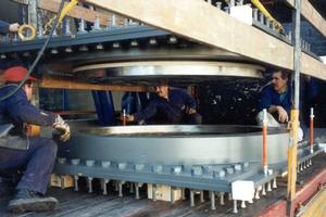
RESTON®POT – Pot Bearings
mageba Pot Bearings are durable bearings that can be used in many situations, whether in big or small bridges, or a variety of engineering structures.
[more]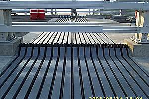
TENSA®MODULAR LR & LR-LS – Modular expansion joints
Modular Expansion Joints can be constructed for any movements, from about 100 mm up to 2,000 mm and more. They allow movements in all 3 directions and rotations around all 3 axes.
[more]Technical description
Load-Bearing Structure
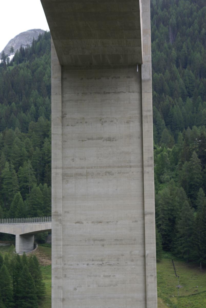
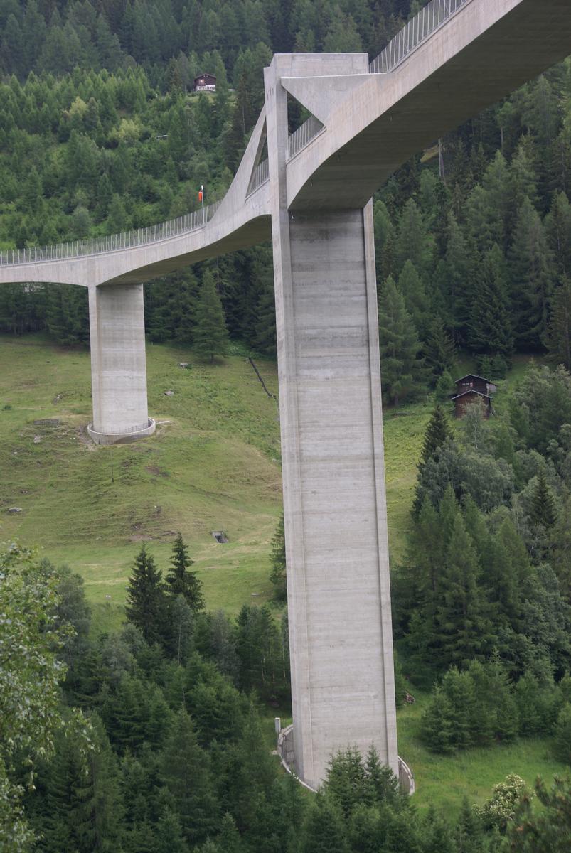
The load-bearing structure of the Ganter Bridge consists of a longitudinally and transversely prestressed jointless eight-span frame. The bridge girder is designed as a rectangular box girder without lateral brackets. The flanges of the two main piers P3 and P4 are raised laterally next to the bridge girder and serve as pylons for the four prestressed tension sheaves. Piers P2 to P7 are rigidly connected to the superstructure; only pier P1 and the two abutments have sliding bearings. Piers P1, P2 and P3 are restrained in the rock on the right side of the valley. The footings of piers P4, P5, P6, and P7 are sliding bearings to compensate for the creep of the left valley slope, and pier footing P4 is temporarily fixed (articulated).
Bearing:
- WL North:
- 2 sliding bearing Na / Nb (side Brig)
- 1 guided bearing Nc
- Pillar P1:
- 2 sliding bearing 1a / 1b
- 1 guided bearing 1c
- WL South:
- 2 sliding bearing Sa / Sb (side Simplon)
- 1 guided bearing Sc
- Pillar P4:
- 2 fixed bearings, PN 10.200 adjustable on sliding surface
- 2 longitudinal force bearings F 560
- 1 transverse force bearing F 780
- Pillar P5 / P6:
- 2 sliding bearings PNGA 2'400 and PNGA 2'900 on sliding surface adjustable
- 1 shear force bearing F 325
- Pillar P7:
- 2 sliding bearings 7a / 7b
Roadway expansion joints:
- WL North (Brig side): 2-section modular expansion joint
- WL South (Simplon side): 5-section modular expansion joint
- .
Prestressing systems:
- Longitudinal prestressing: cable with strands ø 0.50" (1'600/1'800 N/mm²), VSL system
- Cross prestressing: bar tendons (850/1'050 /mm²), Dywidag system
Sealing / surfacing:
PBD bituminous waterproofing membrane / base course HMT 16 N as well as top course AB 11 N
Special equipment:
- Lighting: along the entire length of the box girder
- Safety barriers: guide wall in solid reinforced concrete with lateral guardrail profile A and IPE posts with box section 150 / 180 placed on top of the wall crown.
Anchorages:
- Rock anchorages piers P2 / P3: cable with strands ø 6" (1'600 / 1'800 N/mm²) system Freyssinet
Excerpt from Wikipedia
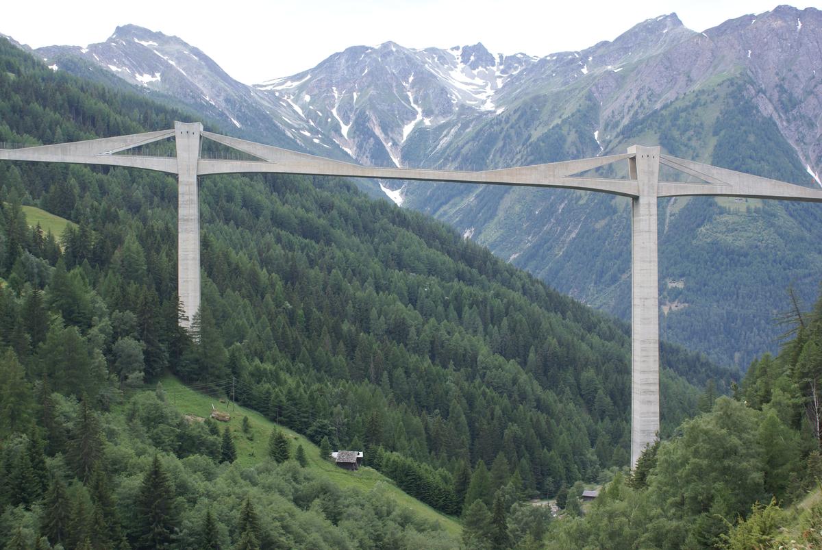
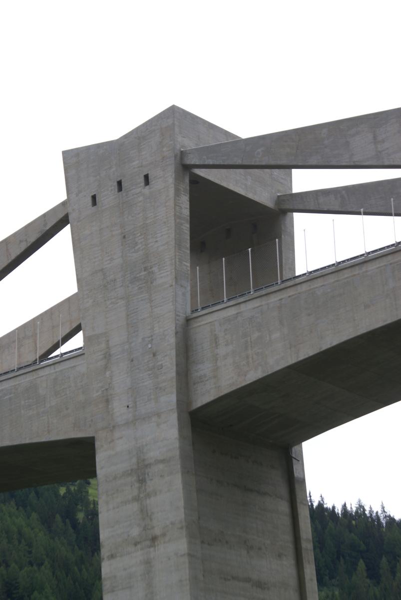
Ganter Bridge is a reinforced concrete road bridge which is the longest spanning bridge in Switzerland, located along the Simplon Pass road in the canton of Valais about 10 km (6 mi) south of Brig. It was designed by renowned Swiss civil engineer Christian Menn and completed in 1980. The overall length is 678 m (2,224 ft) with a main span of 174 m (571 ft), and a maximum tower height of 150 m (492 ft).
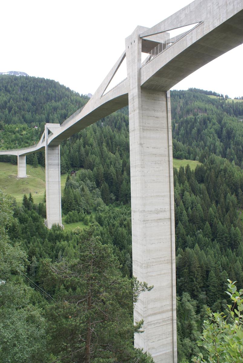
The bridge's form consists of an S-curve high above the Ganter River, at an elevation of about 1,450 m (4,760 ft) above sea level. Two main towers and five smaller piers support a total of eight spans with lengths of 35 m (115 ft), 50 m (164 ft), 80 m (262 ft), 127 m (417 ft), 174 m (571 ft), 127 m (417 ft), 50 m (164 ft), and 35 m (115 ft). The longest span between the two towers is straight, while the remaining spans lie along curves with a radius of 200 m (656 ft).
Its unique design, combining elements of a cable-stayed bridge and a prestressed cantilever hollow-box girder bridge, with triangular concrete walls above the roadway which contain the prestressed cable-stays, has been awarded many prizes. This hybrid type of cable-stayed and girder bridge is sometimes referred to as an extradosed bridge.
Text imported from Wikipedia article "Ganter Bridge" and modified on July 22, 2019 according to the CC-BY-SA 4.0 International license.
Participants
- Christian Menn (designer)
- Blötzer + Pfammatter
- Schneller - Schmidhalter - Ritz
-
Rigendinger / Maag
- W. Maag (structural engineer)
- H. Rigendinger (structural engineer)


Relevant Web Sites

Relevant Publications
- (1996): Advances in Ambient Vibration Testing: Ganter Bridge, Switzerland. In: Structural Engineering International, v. 6, n. 3 (August 1996), pp. 187-190.
- (1997): Christian Menn. Brückenbauer. Birkhäuser Verlag (Basel, Boston, Berlin), Basel (Switzerland), pp. 78-81.
- (2015): Christian Menn - Brücken / Bridges. Scheidegger & Spiess, Zurich (Switzerland), pp. 208-225.
- D'une rive à l'autre / Brücken dieser Welt (6). Le pont du Ganter / Die Ganterbrücke. television documentary, arte, ZDF.
- (1980): Die Entwicklung des Grossbrückenbaus = L'évolution du pont à grande portée = The development of long-span bridge building. 2nd edition, ETH Zürich, Zurich (Switzerland), pp. 188.
- About this
data sheet - Structure-ID
20000026 - Published on:
28/10/1998 - Last updated on:
23/05/2022


