
Semi-active dampers respond to various load cases
Media
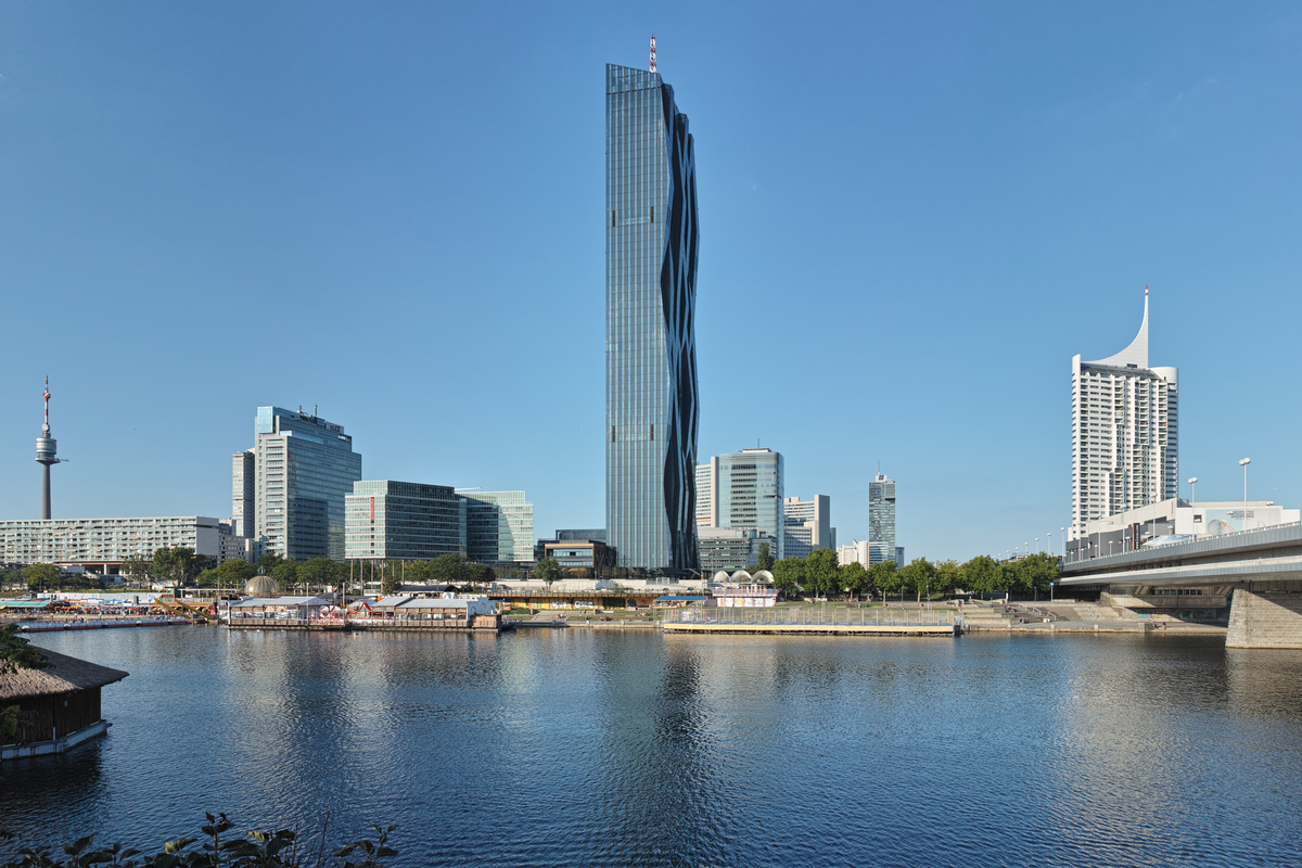
The latest part of Vienna's "Danube City" was designed by the French architect Dominique Perrault who now also signs responsible for this landmark: the two Danube City Towers. One side of the now constructed higher Tower 1 is "ragged" - exactly opposite this half monolith shall receive its slightly smaller counterpart.
With its 59 storeys and a height of 220 m the DC Tower 1 is exposed to wind and would vibrate around its longitudinal axis by up to 45 cm, which is caused by its long ground view and its elastic concrete structure. Moreover, in Vienna even storms or earthquake can occur.
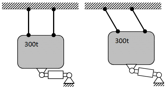
Already at normal wind conditions the comfort criteria and thus the wellbeing of the residents would be diminished. In order to damp the vibrations, between the 56th floor and the top, the tower was equipped with a mass pendulum. The 300 t pendulum mass consists of steel plates and of a water tank, which in case of a fire then can activate its second function. The mass hangs at several steel ropes and acts as a simple transversal pendulum. It swings exactly in opposite direction to the movement of the tower and thus compensates this movement.
So far so good. But these 300 tons also have to be brought under control. This is why the pendulum mass
- will be guided laterally, exactly into the direction of the movement that has to be damped,
- will be damped semi-actively,
- and will receive an end buffer, for safety reasons.
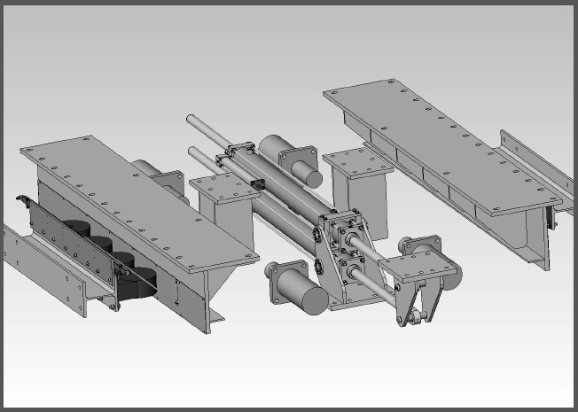
Core element: Semi-active damper
The technical core element is hidden underneath of the pendulum mass. Two semi-actively controlled hydraulic dampers connect the swinging mass with the structure and adapt their reaction to the three load cases "normal wind", "storm", and "earthquake". Base of this unique control are dampers with a magneto-rheologic fluid. Its viscosity can be varied by way of varying the magnitude of a magnetic field. By way of coils and an electric impulse, thus the response force of the damper can be steplessly varied from 3 kN to 110 kN, and this in real time of 50 to 100 msec.
Electric impulses control the response force of the damper
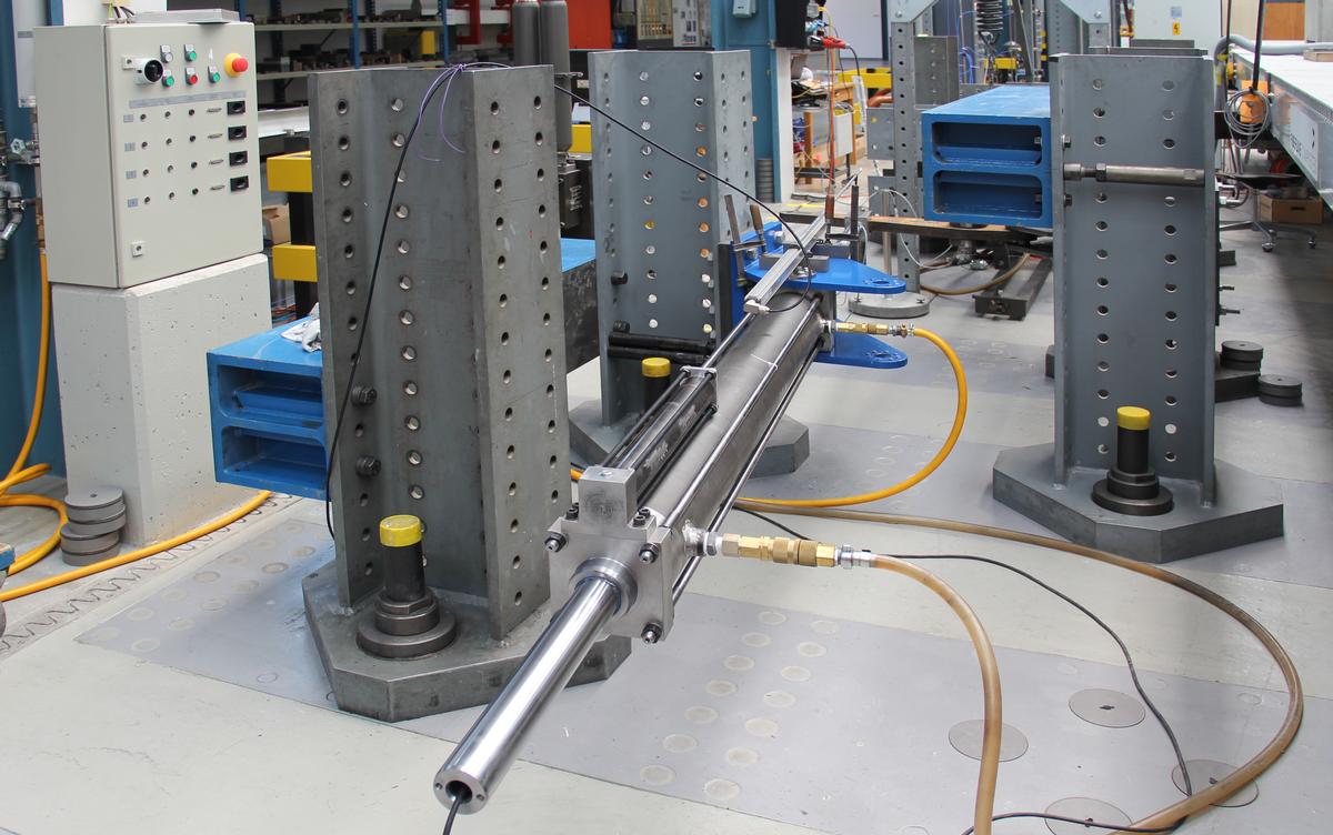
The response force which has to be applied will be determined by a computer that continuously receives data from sensors. This system was tested on a test rig of EMPA located in Dubendorf/Switzerland. "The challenge lies in the correct interpretation of the measured data", explains project manager Peter Huber of MAURER. "On the other hand, the control electronics must provide the right control signals for the optimum damping of the structure. In the building market we are the only company in the world with a know how in semi-active damping." Among others, such semi-active dampers are in service in several bridges, like for example for the damping of stay cables in Wladiwostok (Russki Bridge) or China (Sutong Bridge), or for the mitigation of vibrations of a bridge deck (Wolgograd Bridge, Russia).
For the service stage of the Danube City Tower like frequently occurring wind, the fluid in the damper is very viscous, or highly fluid. In other words, the system is tuned relatively soft: no electric current is active, and the pendulum reduces smallest vibrations of the tower to few millimeters. Should the damper be tuned too stiff, the pendulum would not move and thus would have no effect.
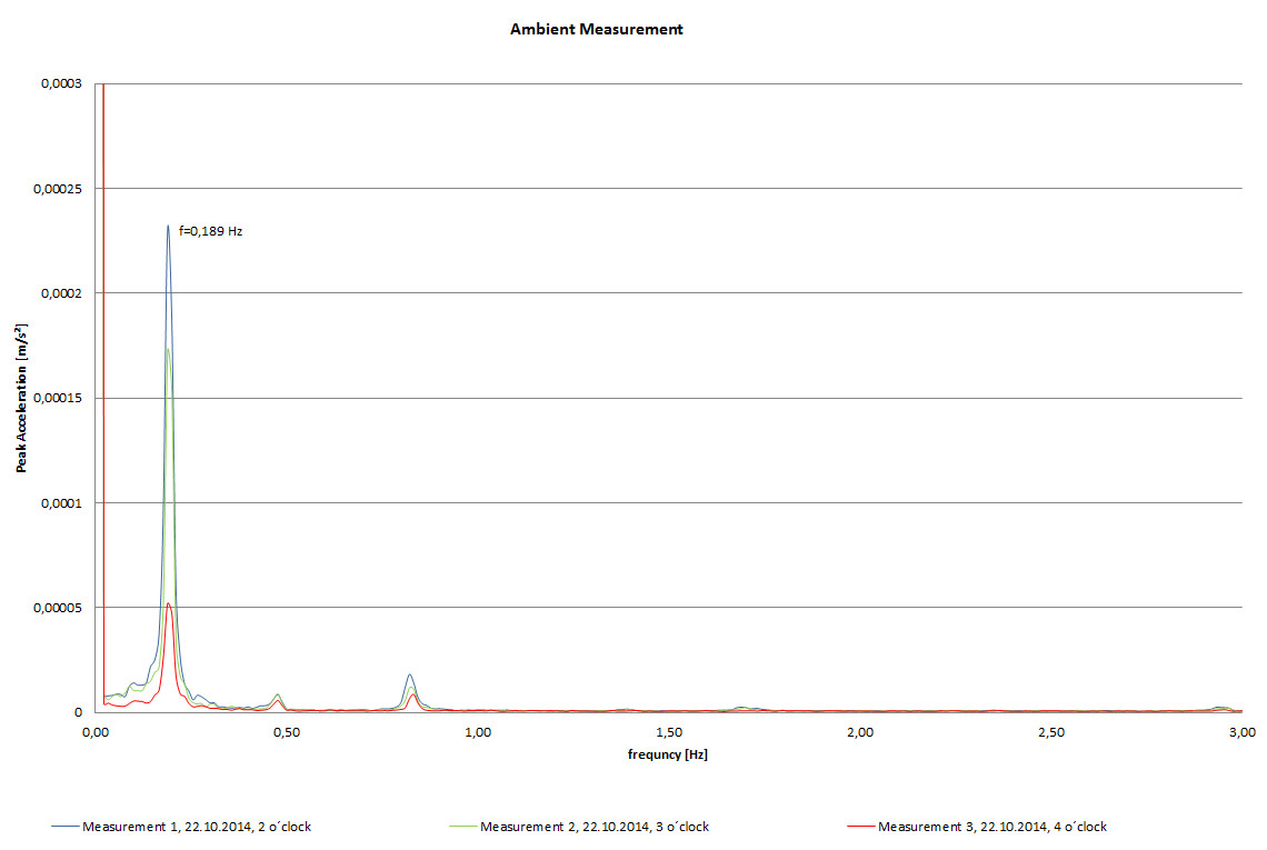
The pendulum length was designed for a frequency of 0.134 Hz to 0.244 Hz. The measured and thus real structural frequency was 0.189 Hz. The semi-active hydraulic dampers can adapt in real time steplessly to a frequency between 0.171 Hz and 0.209 Hz, and thus simulate a real pendulum length of the ropes of between 5.6 m and 8.5 m. Consequently, the lengths of the ropes need not be mechanically adapted.
When the tower und thus also the pendulum deflect more strongly due to strong wind or thunderstorm, also the dampers have to react more strongly.
For the worst assumed load case "Earthquake" or "Centennial Storm", the damped 300 t pendulum can deflect horizontally by up to ±750 mm. The maximum possible and unstopped amplitude of the pendulum was calculated on the base of the design earthquake according Eurocode 8 to be ±2 m. So it had to be limited in order to prevent damages at the tower. "A 300 t swinging mass would penetrate every wall", emphasizes Huber. "This is why the dampers will block at about 550 mm."
Redundant end stoppers
Should the electronics and the battery buffer simultaneously fail, for this ultimate load case a redundant safety system was implemented. Beyond +/-550 mm the pendulum mass hits hydraulic spring dampers. Technologically speaking they are related to end stoppers in elevators. The 4 stoppers will be compressed by 200 mm and thus bring about a response force of max. 470 kN.
Continuous monitoring
It is interesting to know whether the semi-active damper technology is efficient. Given the fact that for the control of the damper anyway all necessary data have to be gathered (like acceleration of the structure, frequencies, amplitudes, and response forces in the hydraulic dampers), they also can be used for the monitoring system. These results are then being compared with the theoretically best and optimum physical degree of efficiency.
For example, if the dampers would in service stage perform too little deflections, the dampers could be tuned more softly. "In the first months everything went according to plan. However so far we had only to deal with the service stage of weak wind", reports Huber.
Heavy load rollers keep 300 t on track
A further necessary detail for the control of the pendulum movements is a horizontal guide. At the bottom and along the long edge of the mass heavy load rollers are fixed. They roll with a minimum friction resistance laterally against steel girders and prevent lateral movements of the mass. Because each movement of the mass into another direction than the one that has to be damped would reduce the efficiency of the 300 t pendulum.
 MAURER SE
 References

Structure Types

- About this
data sheet - Product-ID
7247 - Published on:
07/07/2015 - Last updated on:
19/05/2017