

General Information
| Other name(s): | Wiesbaden Hauptbahnhof |
|---|---|
| Beginning of works: | 1904 |
| Completion: | 15 November 1906 |
| Status: | in use |
Project Type
| Function / usage: |
Railroad (railway) station |
|---|---|
| Architectural style: |
Neo-Baroque |
Awards and Distinctions
| 2015 |
entry
for registered users |
|---|
Location
Technical Information
Dimensions
| track hall | total length | 190.00 m |
| span lengths | 25.45 m - 3 x 17.50 m - 21.05 m | |
| number of spans | 5 | |
| total width | 99.00 m |
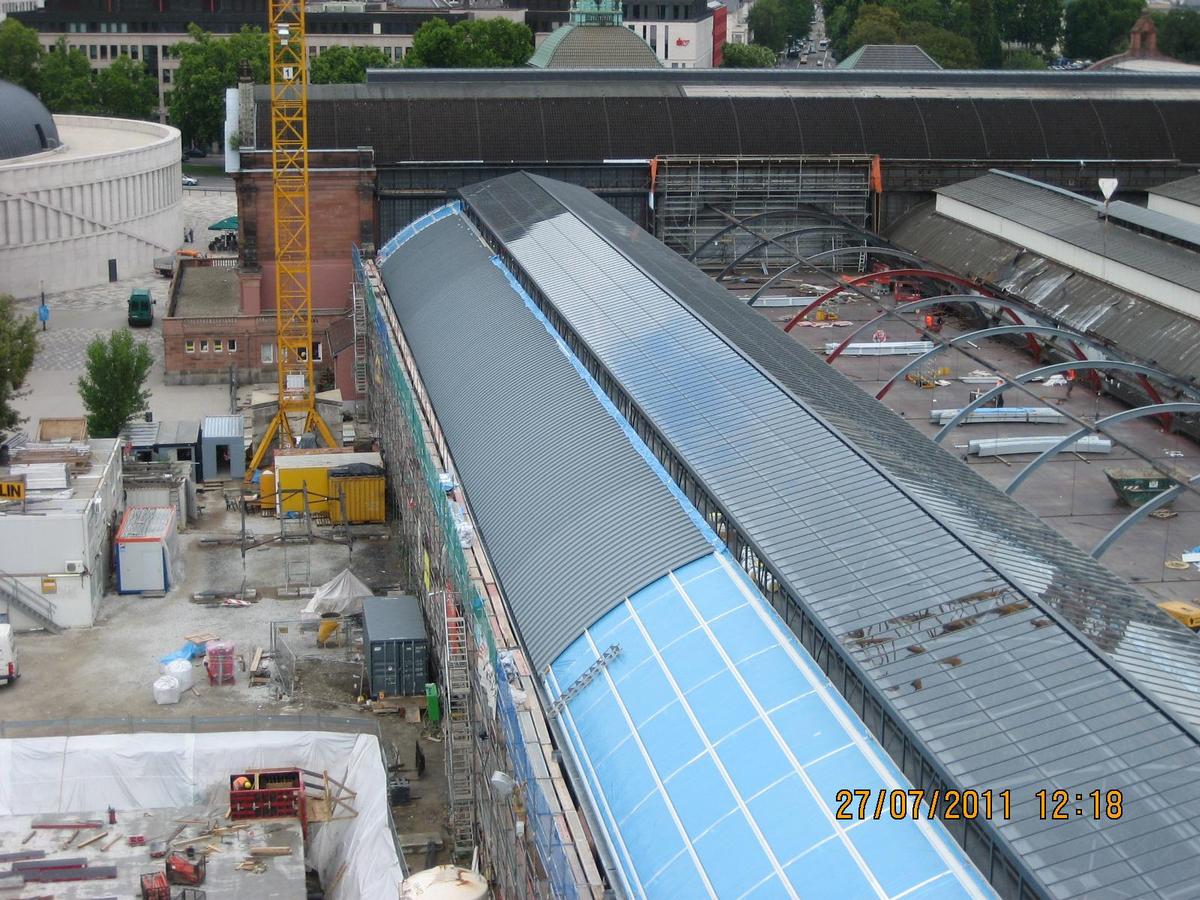
Refurbishment of the platform hall of Wiesbaden main station
Task
The Wiesbaden main station, which is a listed building, consists of the station building with transverse platform and the platform hall, which is directly adjacent to the transverse hall. The platform hall is a more than one hundred year old steel construction with five hall aisles. It was designed in 1904 by the Royal Railway Construction Department in Wiesbaden and built in 1905-1906 by Gutehoffnungshütte Oberhausen, Sterkrade plant.
Over the past decades, significant damage has occurred to the hall structure and facades due to deteriorating roofing and drainage systems.
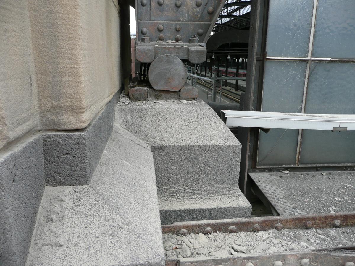
While the coating of the steel structure in the front section of the hall was still encountered in relatively good condition, corrosion was more advanced in the rear section of the hall towards the exit. The arch trusses had localized rusting. In the riveted box columns, considerable loss of cross-section due to leaf rust was observed in the area of the column bases. After exposing the column bases, scar-like severe rusting was discovered, particularly in the area of alternating moisture penetration at the level of the platform surface. The last column axles in front of the hall exit were less protected by the roof and showed the greatest damage. In places, the column walls were rusted through at the base points. The structural inspector's report recorded a total of 42 structural safety-relevant damages for the five hall aisles.
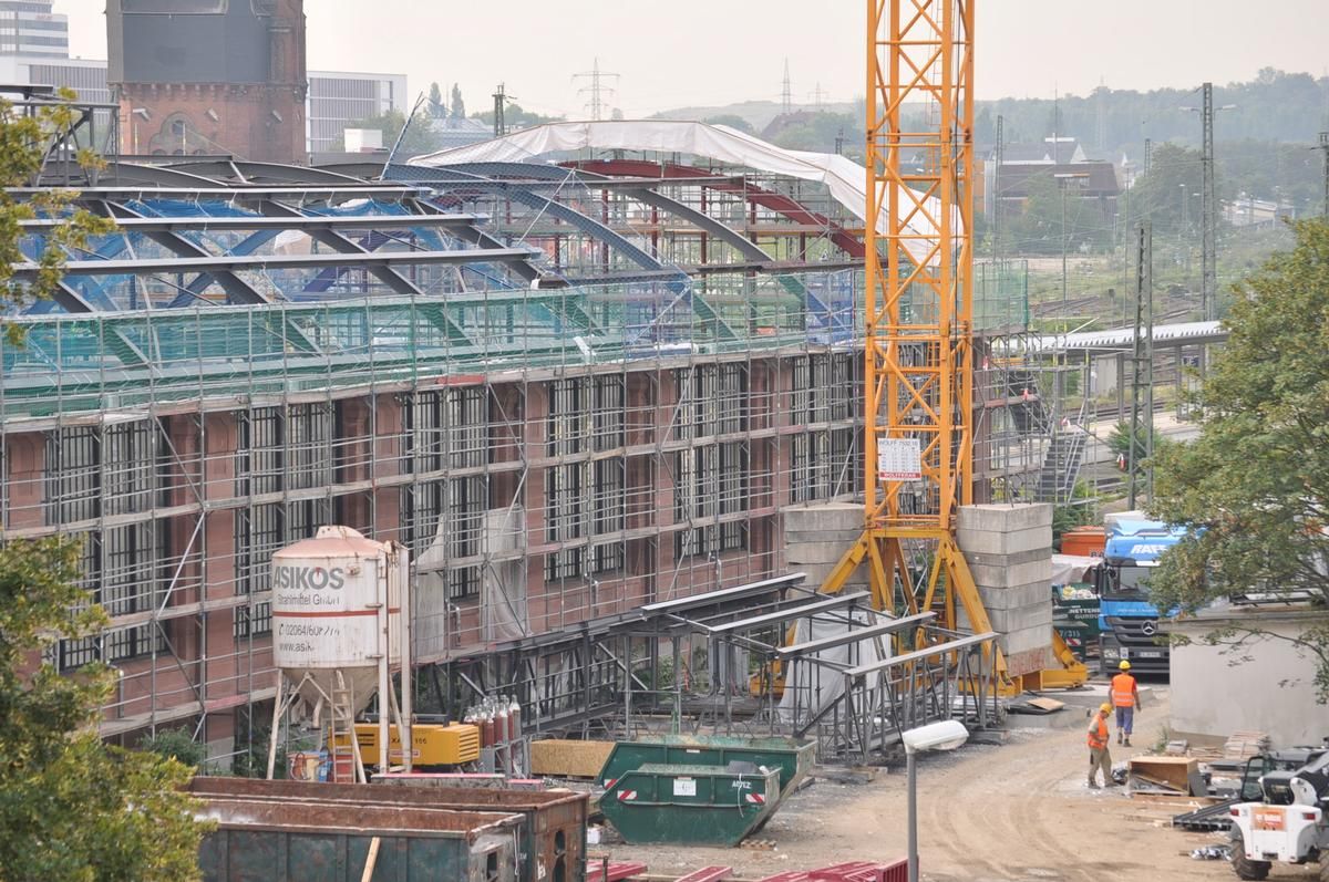
The task was therefore to refurbish and upgrade the platform hall. The steel supporting structure of the roof, which is over a hundred years old, had to be reinforced and provided with new corrosion protection. The roof cladding and roof drainage as well as the glazing of the elevated lanterns had to be renewed. All construction work had to be carried out while the station was in operation.
In the course of the task, the general planning of the work phases 2, 3, 4, 6, 7, 9 was to be provided, the contract also included the structural design for the work phases 2, 3, 4 and 6.
In all renovation measures on the hall roof, the concerns of the protection of historical monuments were always to be taken into account. This applied to both the design implementation and the materials to be used.
Description of the construction
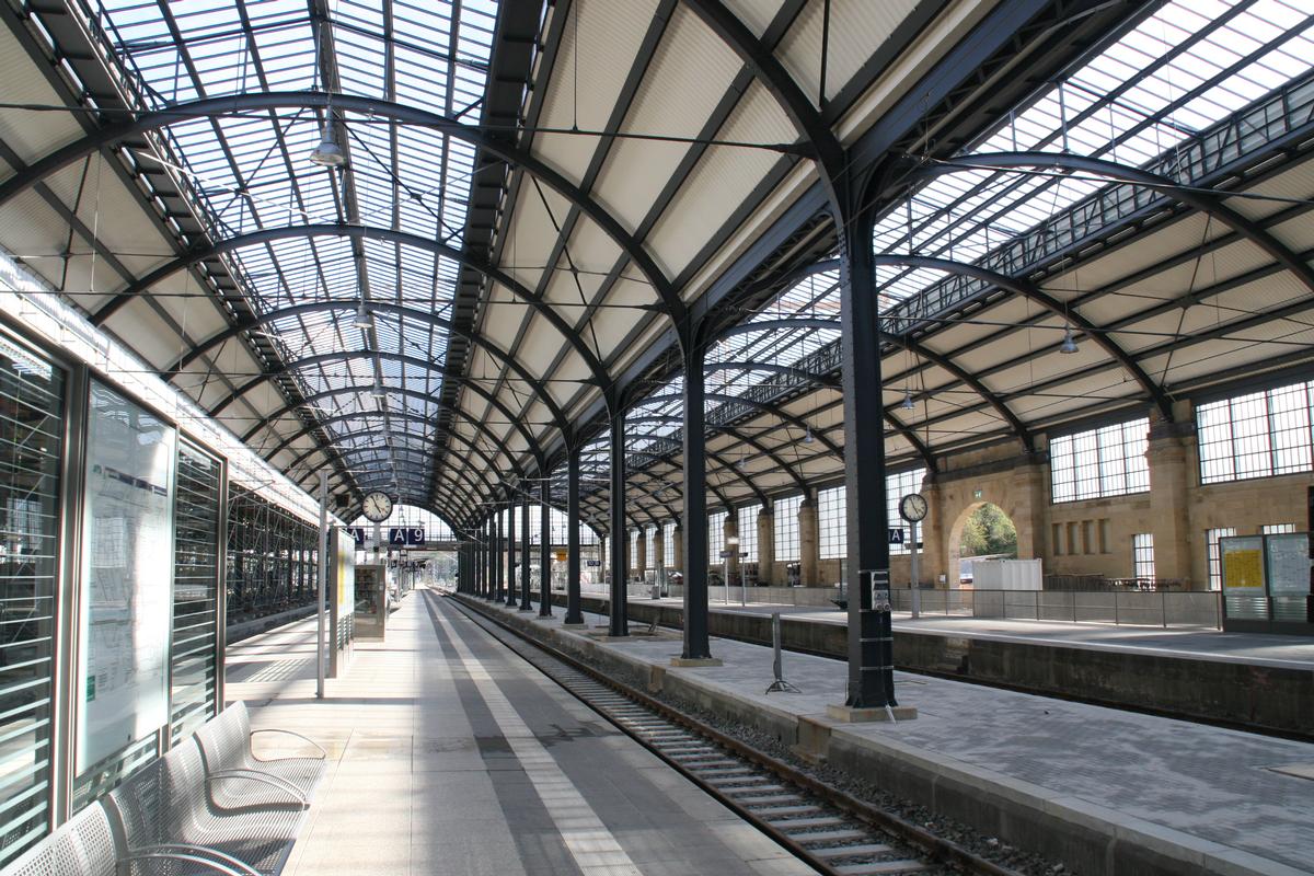
The track hall extends longitudinally over 20 bays, each 9.50 m long, for a total of 190.00 m, and transversely over five ships with spans of 25.45 m – 3 x 17.50 m – 21.05 m, for a total of 99.00 m.
The five ships are spanned by barrel roofs with apexes of equal height. Saddle-roofed glazed lanterns sit on top of the barrel roofs, providing light intake and ventilation. Outside the lanterns, the barrel roofs were covered with cross-span wood sheathing with bituminous sheeting and aluminum lamination. The timber planks rested on steel purlins spanned in the longitudinal direction of the hall and designed as tanner beams.
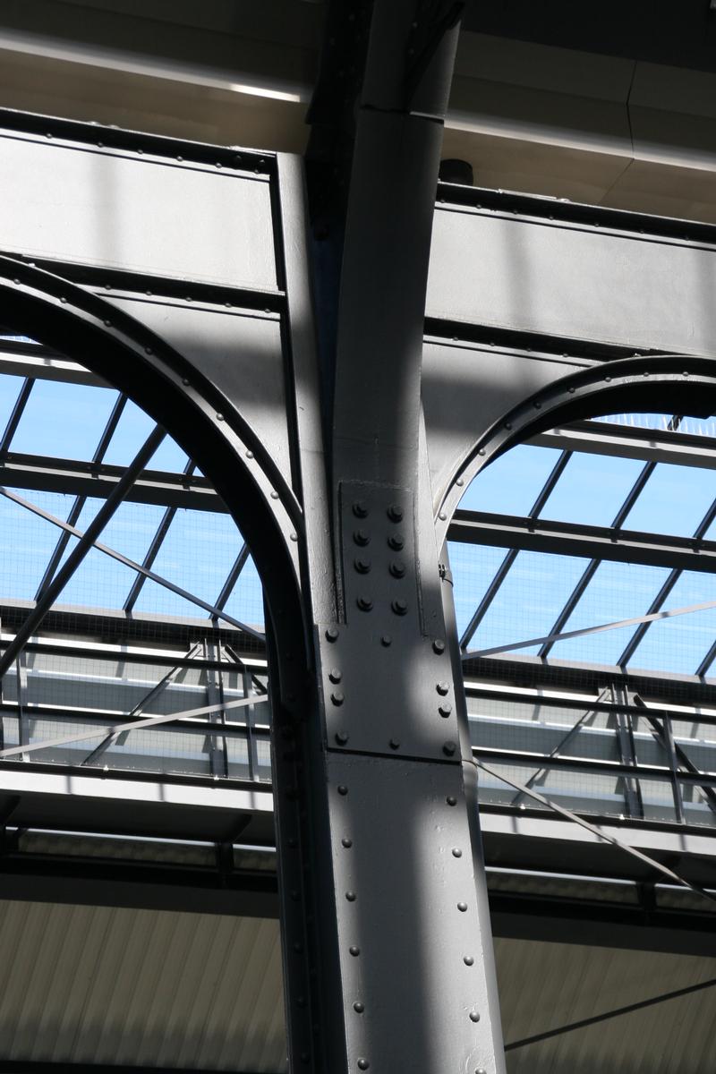
The main supporting structure of the track hall is a riveted steel structure, which has the typical construction features of the time. In the transverse direction of the hall, under-span arch girders have been arranged in the 21 axes, which are supported in the four inner axes B to E by clamped box columns and in the outer axes A and F rest with roller bearings on the outer walls made of sandstone. The arch girders of naves 2 and 4 are flexurally rigidly connected to the columns. The two connections of the arch girder in ship 3 and the connections of the arch girders in ships 1 and 5 to the respective inner support in axis B and E, respectively, are articulated.
Also in the longitudinal direction of the hall, the supports are restrained in axes B to E. In the end bays 1 and 20, longitudinal frames were designed by means of flexurally rigidly connected ledgers at the level of the column heads. In the other bays, the longitudinal ledgers are hinged to the column heads. Bracing is provided in every other truss bay to brace the barrel roofs in the longitudinal direction.
Choice of building materials
A material report on the old steel structure showed that the existing structural steel had approximately the strength properties of an S 235. For material testing, test specimens were taken from the arch trusses, purlins, columns, longitudinal frames and the diagonals of the lanterns. These were subjected to chemical analyses, and tensile tests and notched bar impact tests were also carried out.
As part of the roof renewal, all purlins were replaced with new rolled sections of material grade S 235. The lanterns were rebuilt according to the old design. Angle and U-sections were used for the new components, as in the original construction. In order not to change the appearance of the old steel structure, it was decided to replace profiles only with profiles of the same type and, if possible, not to enlarge the visible surfaces of the profiles.
The lanterns received new roof glazing with laminated safety glass, and the lantern longitudinal walls were clad on the outside with lamellar aluminum sheets that match the original appearance.
The existing roof sheathing and roof drainage were completely replaced. The new roof cladding is a double-skin insulated metal cladding with trapezoidal sheet metal as the supporting shell and standing seam aluminum sheets as the covering shell.
The new roof cladding is a double-skin insulated metal cladding with trapezoidal sheet metal as the supporting shell and standing seam aluminum sheets as the covering shell.
Since a large part of the old steel structure could be reused, especially for the main supporting structure, only 1,400 t of new steel were required. In the course of a sustainability assessment, the steel structure of the hall roofs and the entire refurbishment measure can be certified as having a positive life cycle assessment.
Special engineering service
The basis for the renovation design of the hall roof was a detailed recalculation of the existing structure. In order to be able to calculate and strengthen this as accurately as possible, various preliminary investigations were first carried out. In addition to the material expertise on the old steel structure, the surveying of the hall structure with measurement of the column head displacements and the uncovering of foundations, this also included a wind tunnel investigation on the model to determine the wind loads, since the roof shape of the hall does not correspond to a regulated design.
Due to detailed examination of the damage to the steel structure on site with measurement of the cross-sectional losses caused by rusting and the meticulous planning work in the office with the aid of all as-built documents, it was possible to carry out the necessary structural recalculation. This showed that the old cross-sections of the main load-bearing structure, which consists of under-spanned arched trusses, box columns and longitudinal frames, are stable even under the loads applicable today. In this way, the main steel support structure of the riveted arch trusses could be saved. The planning thus provided for the complete main supporting structure to be retained in its existing condition and provided with new corrosion protection.
It is worth mentioning the imperfection approach adopted for the verification of the supports of the arch trusses. Since notable column head displacements were found during the measurement of the hall, the skew to be applied was calculated back from the measurement results. The pre-torsion from the measurement results, for example, was 1/277 in the transverse direction of the hall as the arithmetic mean of the 20 measured values in the arch plane. Since the ratio between the pre-torsion from geometric and structural imperfection is 1:1 according to the commentary on DIN 18800, twice this value was used as the basic value: 2 x 1/277 = 1/138.
The main design was also verified for structural conditions. It was assumed that the entire roof of a hall aisle is opened one after the other. For these different states of the entire building, wind pressure coefficients were specified in the wind assessment.
The condition for carrying out the main measure was to maintain unrestricted railroad operations and all passenger traffic within the station. Thus, the contractor's work was not to interfere with train traffic or station operations.
The contractor's work was not to interfere with train traffic or station operations.
The renovation design put out to tender provided for the work on the hall roof to be carried out one ship at a time over the entire length, starting at the western ship 5. Since the demolition of the old roof, the corrosion protection work on the arched trusses and the erection of the new roof structure had to be carried out while the railroad was still in operation, the installation of a working platform one ship at a time at a sufficient distance above the contact wire of the overhead line was an ideal solution here.
In order to use the time for preparing the tender documents for the main measure on the construction site, among other things, the rehabilitation of the column bases was to be started early in an advance measure. In addition to the column base reinforcement with corrosion protection up to the lower edge of the longitudinal beams, this advance measure also included the renewal of the window and natural stone facades of the outer longitudinal walls in axes A and F. With this planning during construction, a significant shortening of the overall measure was achieved. Among other things by this and by providing a checked static calculation for the hall roof with the award of contract to the contractor, the renovated platform halls could be completed one year earlier than originally planned.
Explanatory report by Wihermüller & Vogel Ingenieure for submission to the Ulrich Finsterwalder Ingenieurbaupreis 2015
Excerpt from Wikipedia
Wiesbaden Hauptbahnhof is a railway station for the city of Wiesbaden, the state capital of the German state of Hesse. It is a terminal station at the southern edge of the city centre and is used by more than 40,000 travelers each day, so it is the second largest station in Hesse after Frankfurt Hauptbahnhof. It is classified by Deutsche Bahn as a category 2 station.
History
The current station replaced three stations in the city centre, which were next to each other near the fairground (Rhein-Main-Hallen) and the Wiesbaden Museum. These were:
- The Taunusbahnhof (Taunus station), built in 1840 for the Taunus Railway (Wiesbaden–Castel–Höchst–Frankfurt (Taunusbahnhof).
- The Rheinbahnhof (Rhine station), built in 1857 for the East Rhine railway (Wiesbaden–Biebrich–Rüdesheim–Niederlahnstein).
- The Ludwigsbahnhof (Ludwig's Railway station), built in 1879 for the Ländches Railway (Wiesbaden-Niedernhausen).
A fourth railway line was added in 1889, connecting to the Rheinbahnhof, with the opening Langenschwalbach Railway (now the Aar Valley Railway— Aartalbahn) from the Rheinbahnhof in Wiesbaden to Bad Schwalbach (then called Langenschwalbach) and later extended to Diez on the Lahn.
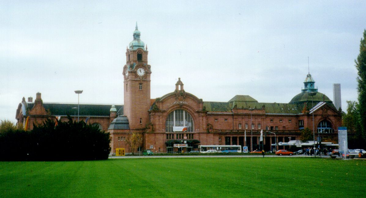
The new station building became necessary to handle the growing number of passenger visiting the spa city at that time. It was built from 1904 to 1906 according to the plans of Fritz Klingholz in a flamboyant neo-baroque style that corresponded to an international style of architecture adopted for spa towns. It was also intended to welcome Kaiser Wilhelm II on his visit to the spa every May and a platform was established for him and other aristocrats. The first train ran into the new station on 15 November 1906 around 2:23 a.m. In the station building the relics of the former images of crowned heads, with the faces removed, can still be seen in many places.
The new Hauptbahnhof was located outside the town at the time of its building at the south-eastern end of the then newly constructed ring road (the Kaiser-Friedrich-Ring and the Bismarckring), which runs in an arc to the west of the historic pentagon (Historische Fünfeck) at the centre of Wiesbaden. During the period up to the First World War the town developed towards the new station.
On 25 September 1983, the Hauptbahnhof was affected by the closure of a line. Passenger services were discontinued between Wiesbaden and Bad Schwalbach on the Aar Valley Railway. One of the long-term consequences was the decommissioning and dismantling of station track 11 so that the station now has only 10 tracks.
Wiesbaden Hauptbahnhof was extensively refurbished and modernised at a cost of €25 million between 2003 and 2004. A redesign of the forecourt, costing €1.5 million, was carried out between mid-2006 and March 2007. The modernisation should have been completed with the opening of the high-speed line to Cologne, but was postponed several times due to lack of funds.
Next door is the Lilien-Carré shopping centre opened in March 2007 on the site of the former main post office.
As part of the economic stimulus package, the train shed roofs have been renovated at a cost of €35 million since late 2010.
Connection to the Cologne-Frankfurt high-speed line
Wiesbaden Hauptbahnhof is connected to the Cologne-Frankfurt high-speed line by the approximately 13.0 km long Breckenheim–Wiesbaden line opened in 2002.
This line had been subjected to extensive analysis and discussions by 1990. Three options were investigated:
- an alignment of the main route of the high-speed line through Wiesbaden station. This option was originally premised on the route of the line running generally along the eastern bank of the Rhine, which was rejected after exhaustive investigations. It examined possible connection to the current station:
- by continuing to serve the terminal station,
- with the construction of a new underground station deep near the existing station area, running north–south, and
- with the construction of a new underground station, running east-west;
- an alignment on the eastern outskirts of Wiesbaden, with sub-variants with or without the construction of a new station. Possible station sites were tested in the Hainerberg district (more than a kilometre east of the Hauptbahnhof), near Wiesbaden Ost station and east of the Bierstadt district. Only in the case of Wiesbaden Ost was a link to the S-Bahn possible and in all three cases connections to public transport (especially buses) would have had to be changed.
- an alignment along the A3 to the east of Wiesbaden.
The option of running under the Wiesbaden city area with a station on a north-south orientation was dismissed. Overall, this option required an ascending 10.2 km tunnel. Also rejected was the east-west option as it would have required a tunnel that was located 30 to 100 m below the water table. The high pressure of ground water under parts of the city of Wiesbaden made this extremely difficult. Test bores on the route of the postulated tunnel found material that was penetrated by debris.
In August 1991, the state of Hesse, the city of Wiesbaden and the Deutsche Bundesbahn agreed to a ground-level connection running from the Hauptbahnhof via a link to the east to the new line. The realised Wiesbadener Kreuz (Wiesbaden Cross) option was accessed as having the best cost-benefit ratio. A major argument put forward in the assessment report was that the best way by far of generating passenger traffic would be a connection to the existing station and that only at Wiesbaden Hauptbahnhof would it be possible to give comprehensive access to public transport. Furthermore, the option largely agreed with the route promoted by nature conservation and environmental groups.
A proposed branch off the link along the A 66 and connecting to the high-speed line towards Frankfurt, which would be served only by regional services has not been realized. As part of the connection to the new line, a platform in Wiesbaden station was extended to the length of long ICE trains. The cost of €1.7 million were funded by the federal government.
Patronage of services on the line have been disappointing and services have been cut back from those originally operating so that there are now only two services each way on week days only.
Architecture
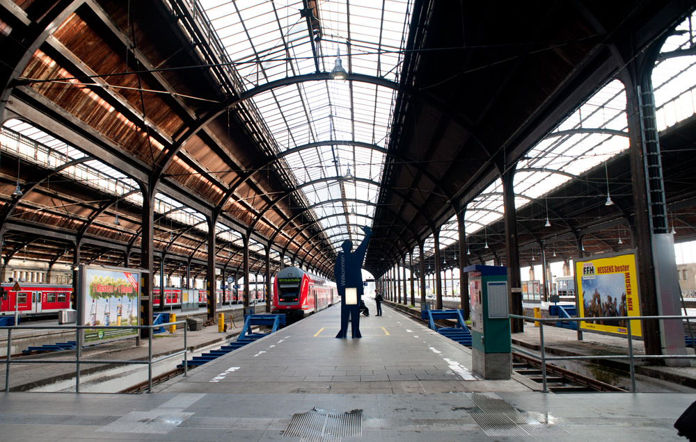
The station building is connected to a five-span train-shed, originally with eleven tracks (now only ten are in operation), which are located in front of a broad vaulted concourse that extends eastward beyond the train-shed and at right angles to it to a vaulted lobby to the east of platform track 1.
The exterior is formed of red sandstone and has rich Baroque Revival forms. The highlight is the lobby on the eastern side, which has a 40-metre-high (130 ft) clock tower with a curved canopy. The former entrance on the western side is surmounted by a copper dome. The roof is adorned with green tiles.
The interior of the building is formed of yellow sandstone, in contrast to the exterior. The roof over the actual platform area consists of steel and glass.
During its renovation in 2004, the station was largely restored to its original appearance. The monumental nature of the concourse is now restored to its full advantage as distracting objects have been removed.
Text imported from Wikipedia article "Wiesbaden Hauptbahnhof" and modified on July 23, 2019 according to the CC-BY-SA 4.0 International license.
Participants
- Fritz Klingholz (architect)

- Ekkehard Fehling (checking engineer)
Relevant Web Sites

Relevant Publications
- (2012): Sanierung der Bahnsteighalle des Wiesbadener Hauptbahnhofes. In: Stahlbau, v. 81, n. 7 (July 2012), pp. 519-529.
- About this
data sheet - Structure-ID
20023195 - Published on:
01/10/2006 - Last updated on:
21/04/2016


