
Design of bearings for the Queensferry Crossing, Scotland
A special design has been developed for the vertically-oriented bearings between the towers and the deck of the Queensferry Crossing across the Firth of Forth.
The decks of long-span, cable-stayed bridges are often subjected to horizontal loads that are too large to be resisted by typical, horizontally oriented guided bearings. In such cases, vertically oriented sliding bearings can be used in pairs to resist the large transverse forces. These can be attached at each side of a so-called shear key or wind shoe, or, as in the case of the Queensferry Crossing in Scotland, directly to a tower between it and the deck.
Vertically-oriented bearings that are used in this way to resist large transverse forces are subject to in-service challenges that do not apply to traditional bridge bearings. Since the bearings operate in pairs that are separated by some distance - for example by the width of a shear key or a tower - deformations of the main structure can be hugely significant for the bearing design. Such deformations can arise for several reasons including structural temperature variations, concrete shrinkage and creep, the ‘wedge effect' that can result when the sliding surfaces of a pair of bearings are not perfectly parallel, deck rotations relative to the substructure - about longitudinal/vertical axes - and transverse strain due to vertical compression and longitudinal flexure (Poisson's ratio). Any such deformation can cause the clear width of the gap in which a bearing is located to increase or decrease.
If the gap width increases, the bearing's sliding interface will come apart. This increases the risk of contamination and could lead to damaging impacts as the deck moves transversely thanks to its new-found freedom. Indeed, depending on the bearing design, the bearing might even fall apart when no longer under compression; in the case of a spherical bearing, for example, the calotte could simply fall out.
On the other hand, if the gap width decreases, enormous constraint forces could build up, potentially causing severe damage to the bearing or the main structure. Hence the bearings must be designed to accommodate varying gap widths. This can typically be best achieved by incorporating elastically-deforming elements which can expand and contract while always in a state of compression, thus enabling the entire bearing to remain in a state of compression while accommodating changes in gap width. A preload must generally be applied to the elastically-deforming elements in order to ensure that they remain in a state of compression at all times, even when the gap width increases to the maximum extent.
Design of bearings presented a demanding challenge
The design of bearings for the Queensferry Crossing, which is currently under construction across the Firth of Forth near Edinburgh, Scotland, presented a particularly demanding challenge. The new bridge is being constructed on behalf of Transport Scotland by the Forth Crossing Bridge Constructors, a consortium formed by Hochtief, Dragados, American Bridge and Morrison Construction. The final design was undertaken by a joint venture comprising Grontmij, Gifford, Ramboll and Leonhardt Andrä & Partner, based on a specimen design by a Jacobs Arup joint venture.
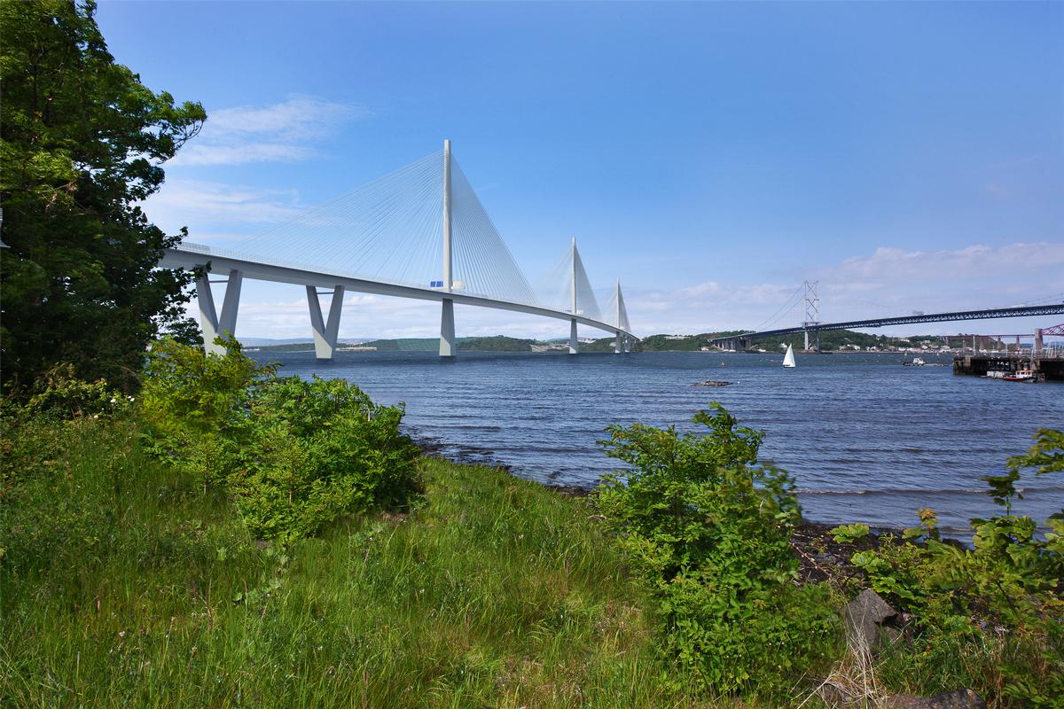
The longest three-tower, cable-stayed bridge in the world
Not only will the 2.7 km structure be the longest three-tower, cable-stayed bridge in the world, it will also be by far the largest to feature cables that cross mid-span. The superstructure has a composite design with a concrete deck slab, a steel box girder and two main spans of 650 m each. While the superstructure is fixed to the central tower, its connections to the two flanking towers are designed to prevent transverse movements only. In order to achieve this while allowing longitudinal movements, the flanking towers are equipped with vertically-oriented sliding bearings at each side to transmit transverse wind forces from the superstructure. Due to the size of the tower the spacing between the bearings is 10 m - a large value considering the previously described challenges for vertically-oriented bearings acting in pairs.
To address the challenge, which included a 17 MN design load (ULS) for each bearing, it was decided to develop an EN1337-2-based design using a Reston spherical bearing and the Robo-Slide ultra-high-molecular-weight polyethylene sliding material. Reston spherical bearings comprise a spherically-shaped calotte and a concave seat that transfer vertical forces while allowing the required rotations. They ensure the controlled transfer of forces between superstructure and substructure while facilitating rotations about every axis and movements in every direction.
Robo-Slide is an alternative material to PTFE in sliding bearings, with enhanced characteristics including far higher durability. The use of these bearings was predicted to minimize the size and weight of the bearing for the given loading while accommodating large rotations and facilitating both installation and future replacement work. The bearing is designed with a separate anchor plate for the connection to the bridge deck, and a large stainless steel sliding plate on the tower faces the Robo-Slide surface on the calotte.
Considering all possible causes of constraint forces, it was concluded that the bearing design had to allow a movement range across the bearing of approximately 30 mm in order to ensure that the bearing's sliding surface would not become overloaded in any circumstances. Furthermore, a number of modifications were required to the standard spherical bearing design to prevent the separation of the bearing's sliding interface as the gap between the connecting bridge structures opened.
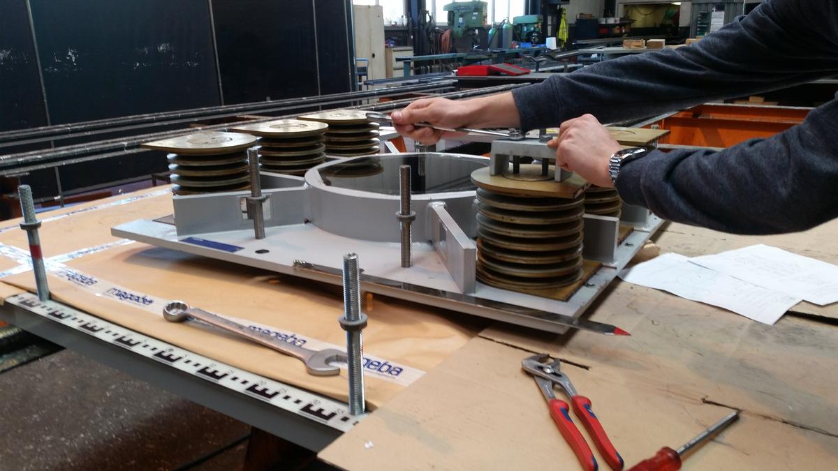
Firstly, the bearing's anchor plate is keyed into the concave seating like a piston, enabling the bearing to expand and contract but not, at this interface, to accommodate any other movements. Six disc springs are arranged around the seating's concave sliding surface between the seating and the anchor plate. These springs are in a constant state of compression, regardless of gap width, due to the appropriate pre-loading. They exert a constant force on the seating, pressing the calotte that it supports against the sliding plate on the tower. As a result of the preloading of the disc springs, the minimum contact pressure at the sliding interface and at the maximum design gap is 0.7 MPa. This ensures that the gap will never open and that the bearing will never fall apart. In addition, the ability of the springs to compress further ensures that damaging constraint forces will never arise. This low-maintenance, high-durability, technically optimized solution fulfills all the necessary requirements for the construction of this exceptional structure.
Authors:
Max Brüninghold is research & development engineer (bearings), Niculing Meng is chief sales officer; both work for mageba.
 mageba group
References
.jpg)
Queensferry, Edinburgh, Scotland, United Kingdom, Europe - North Queensferry, Fife, Scotland, United Kingdom (2017)
Structure Types

- About this
data sheet - Product-ID
7460 - Published on:
24/01/2017 - Last updated on:
17/11/2021