
General Information
Project Type
| Function / usage: |
Road bridge |
|---|---|
| Structure: |
Cable-stayed bridge with semi-fan system |
| Secondary structure(s): |
Structurae Plus/Pro - Subscribe Now! |
| Structure: |
Two-span cable-stayed bridge |
| Material: |
Structurae Plus/Pro - Subscribe Now! main bridge: Steel-reinforced concrete composite bridge Structurae Plus/Pro - Subscribe Now! approach viaducts: Prestressed concrete bridge |
| Secondary structure(s): |
Structurae Plus/Pro - Subscribe Now! |
Awards and Distinctions
| 2015 |
entry
for registered users |
|---|
Location
| Location: |
Schönebeck (Elbe), Salzlandkreis, Saxony-Anhalt, Germany |
|---|---|
| Address: | B 246a |
| Crosses: |
|
| Coordinates: | 52° 1' 24.52" N 11° 45' 29.68" E |
Technical Information
Dimensions
| total length | 1 128.50 m | |
| deck width | 11.60 m | |
| bridge surface | 13 091 m² | |
| piles | diameter | 1.20 m |
| main bridge | ||
|---|---|---|
| main span | 185 m | |
| total length | 489.00 m | |
| span lengths | 34 m - 4 x 38 m - 3 x 40 m - 185 m | |
| number of spans | 9 | |
| pylon | pylon height | 73.3 m |
| northern approach viaduct | ||
| total length | 330.50 m | |
| span lengths | 36 m - 6 x 43 m - 36 m | |
| number of spans | 8 | |
| southern approach viaduct | ||
| total length | 309.00 m | |
| span lengths | 32 m - 44 m - 34 m - 39 m - 3 x 42 m - 34 m | |
| number of spans | 8 | |
Quantities
| parapets | concrete volume | 1 280 m³ |
| reinforcing steel | 185 t | |
| piles | total length of piles | 200 m |
| substructure | concrete volume | 7 690 m³ |
| reinforcing steel | 930 t | |
| approach viaduct | ||
|---|---|---|
| deck | concrete volume | 11 670 m³ |
| reinforcing steel | 1 270 t | |
| longitudinal prestressing | 366 t | |
| main bridge | ||
| deck | structural steel | 1 120 t |
| concrete volume | 655 m³ | |
| reinforcing steel | 230 t | |
| pylon | structural steel | 180 t |
| concrete volume | 1 070 m³ | |
| reinforcing steel | 340 t | |
| stay cables | steel for cable-stays | 180 t |
Design Loads
| live load | LM 1 | |
| design code(s) | DIN FB 101 |
Cost
| cost of construction (incl. taxes) | Euro 31 400 000 |
Materials
| pylon |
reinforced concrete
|
|---|---|
| piers |
reinforced concrete
|
| deck of main bridge |
composite steel-reinforced concrete
|
| deck of approach viaduct |
prestressed concrete
|
| abutments |
reinforced concrete
|
New construction of the Schönebeck Elbe River bridge
Task definition
The new Schönebeck Elbauenbrücke bridge is the most important part of the Schönebeck bypass of the B 246a federal highway, which consists of a total of 3 construction phases.
With the completion of the Elbauenbrücke the city center of Schönebeck will be relieved of the greatly increased through traffic, at the same time a new efficient connection between the BAB A14 Halle-Magdeburg and the East Elbe areas is created.
The nature at the planned bridge site is mainly determined by the Elbe river with its wide flood plains and causes special requirements for the protection of flora and fauna during the construction of the Elbe crossing.
Description of the construction and choice of construction materials
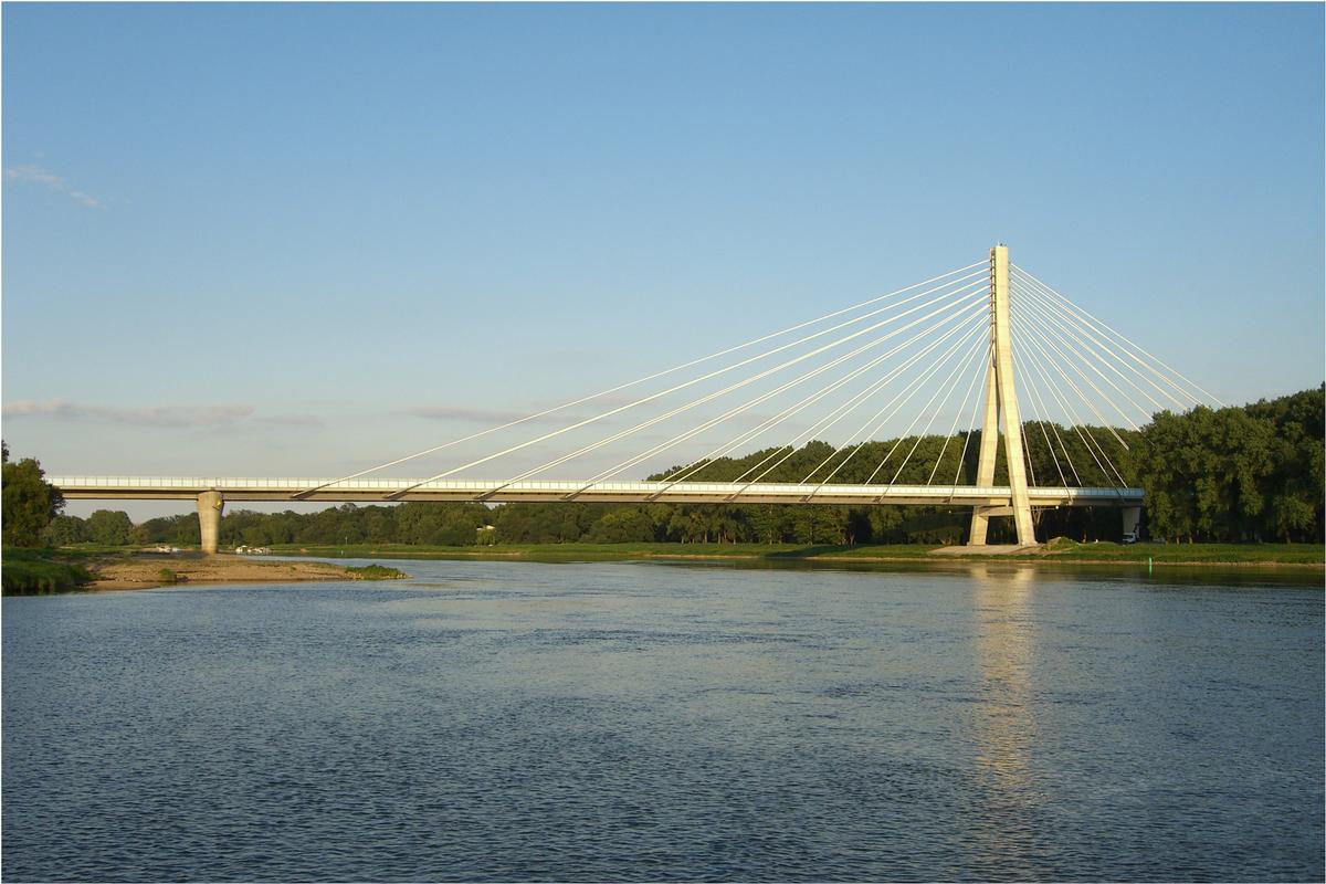
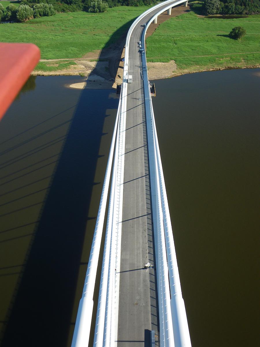
After extensive route options, a bridge span totaling 1,129 m between the Elbe dikes was chosen for the new structure. The route, coming from the southeast, runs in a radius of 340 m over the southern foreland, turns into a 520 m long straight line and crosses the Elbe at right angles. It then passes the northern foreland in another curve with a radius of 340 m. Due to the chosen alignment, the main bridge over the Elbe is still visible coming from both directions of travel, which had to be taken into account in the design of the bridge.
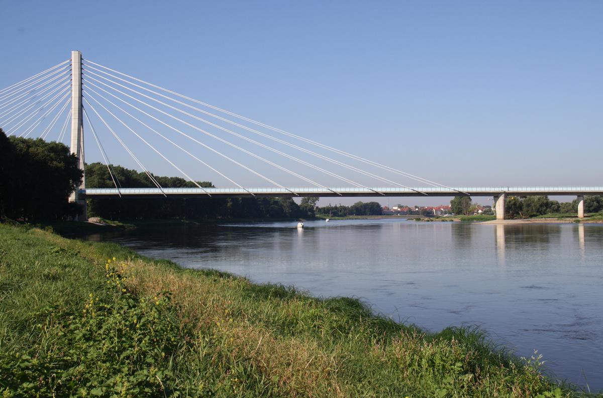
In view of the exposed location of the structure, the design pursued the goal of designing a bridge that would fit harmoniously into the existing, sensitive Elbe meadow landscape, that could be economically constructed and maintained, and that would take into account environmental protection concerns. Particular attention was paid to the design effect in the surrounding city-river landscape, which is defined on the southern bank of the Elbe by the silhouette of Schönebeck's old town and upstream by floodplain forests near the Elbe.
The 1129 m long bridge train consists of the 309 m long southern foreshore bridge, the 489 m long river bridge and the 331 m long northern foreshore bridge. In the area of the foreshore bridges and the side spans of the Strombrücke, the approximately 12 m wide superstructure is designed as a solid slab in prestressed concrete.
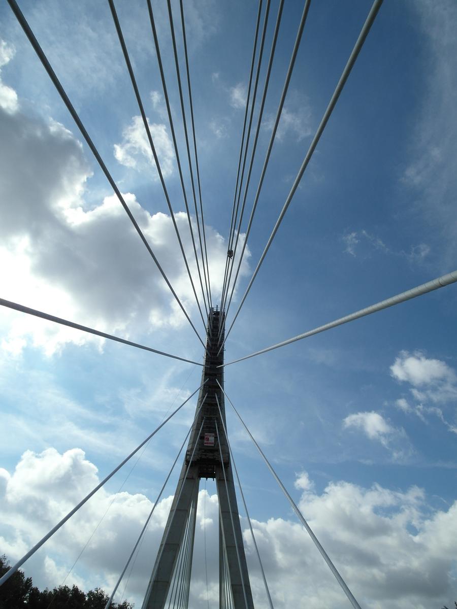
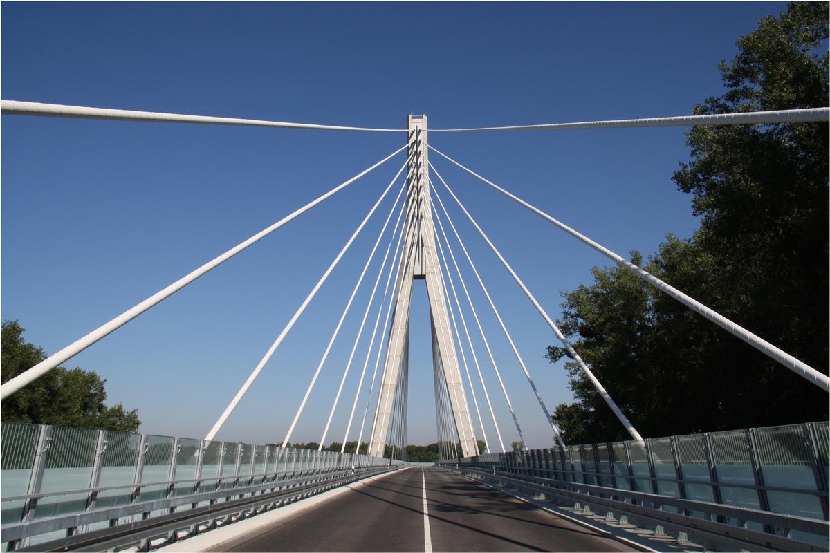
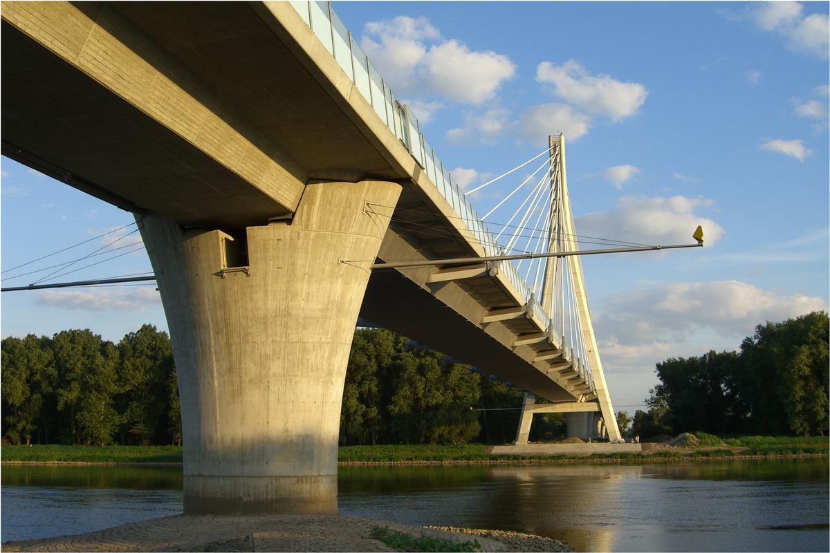
The Strombrücke is a single-sided cable-stayed bridge with a left-island pylon, a span of 185 m and three side spans with a span of 40 m each. The arrangement of the stay cables is fan-shaped in two cable levels. The cable spacing was set at 18.5 m for structural reasons and in consideration of the avifauna. In the area of the current field, the superstructure is designed as an airtight welded, single-cell, closed composite box girder. In addition to its high torsional stiffness and the resulting lower susceptibility to vibration, the box girder results in a closed, quiet bridge soffit. In the process, the composite deck slab in the cantilever area was made of semi-precast parts, so that the use of a formwork carriage could be dispensed with.
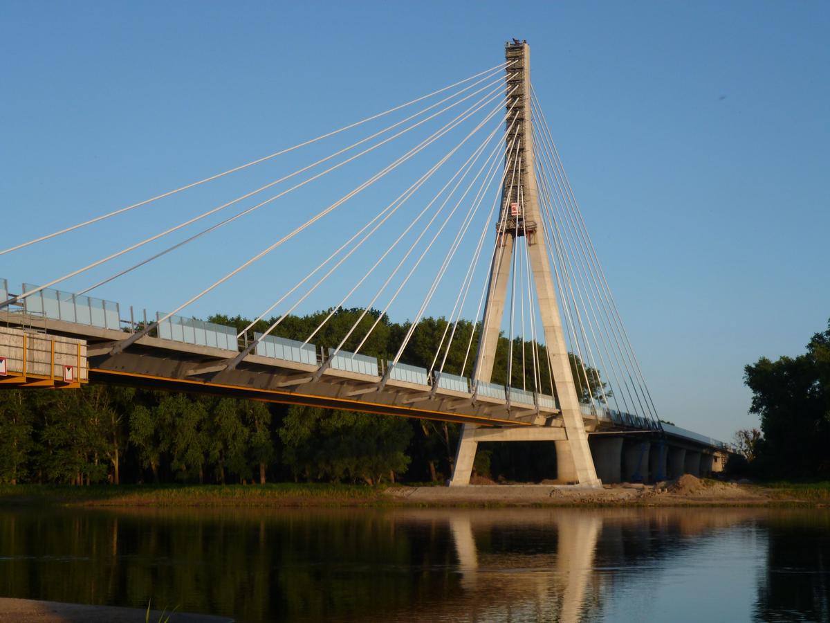
The appealing design of the 73 m high pylon as a dominant feature in the surrounding landscape is of crucial importance. For the bridge, which stands freely in the landscape with its narrow traffic route, the classic A-pylon proves to be the most suitable here.
Its shape reflects the direct flow of forces from the pylon head to the foundation, taking into account both the structural requirements of the cable anchorages and those of continuous accessibility. The pylon head with composite cross-section appears slender and clearly structured due to the visible hollow steel box for accommodating the cable anchorages. The reinforced concrete shafts have a slight rounding that continues into the pylon head and gives the pylon an elegant curve. The continuation of the design in the reinforced concrete bridge piers and abutments supports the harmonious overall appearance. A functional solution that corresponds to the flow of forces is always characterized by its clarity in an appealing design.
Due to the soil water attacked by existing salt deposits, the bridge is designed as a shallow foundation in closed sheet pile boxes in all structural axes. In the pylon axis, unreinforced large-diameter bored piles up to 6 m long have been installed below the foundation in order to favorably influence the settlement behavior for the foundation loads of up to 140 MN concentrated at the pylon. The large-bore piles are specifically located under the pylon shafts and tie into the underwater concrete base located under the foundation for another approx. 1 m.
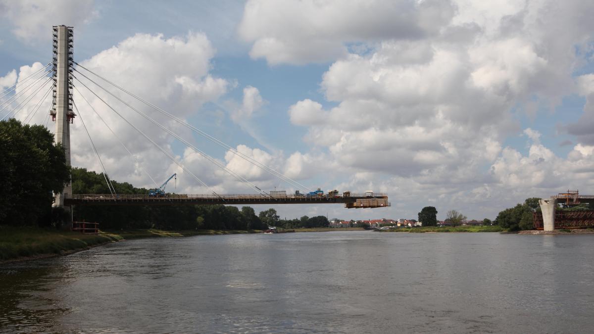
The superstructure was erected in the cantilever method in a total of eleven shots using a mobile slewing crane from the superstructure. Due to this type of assembly, special considerations were necessary with regard to the determination of the rope forces and the formation of the deck. In contrast to the derrick, a mobile crane represents a changing load on the load-bearing system, which was taken into account accordingly in the planning.
Special engineering achievement
The Elbauenbrücke Schönebeck is characterized in its entirety as well as in detail by a clear functional design, whereby the flow of forces can be experienced by the viewer of the bridge. It is a positive example of the creative potential of German civil engineering, which today presents itself in a variety of technical, design and economic possibilities. According to the requirements and boundary conditions, different structural systems and materials were selected and successfully executed within this structure according to their best suitability.
Innovative is the cable anchorage with special anchor tubes in the solid cross section, for the first time parallel strand bundles were tendered and realized as an official design.
Despite its size, the structure blends in well with the surrounding landscape and will become a new landmark for the Schönebeck region.
Explanatory report by Leonhardt, Andrä und Partner. Beratende Ingenieure VBI AG on the submission to the Ulrich Finsterwalder Ingenieurbaupreis 2015
Participants
- Gerhard Hanswille (checking engineer)
- Michael Müller (checking engineer)

Relevant Web Sites
There currently are no relevant websites listed.
Relevant Publications
- Brücken und Tunnel der Bundesfernstraßen 2014. Bundesministerium für Verkehr und digitale Infrastruktur, Berlin (Germany), 2014, pp. 45-59.
- (2013): Entwicklungspotenzial im Straßenbrückenbau durch den Einsatz von hybriden Tragstrukturen - Teil 2: Schrägseilbrücken. In: Stahlbau, v. 82, n. 11 (November 2013), pp. 851-867.
- (2015): Mit leichtem Schwung über die Elbe - Die neue Elbebrücke Schönebeck. In: (2015): Ingenieurbaukunst 2016. Ernst & Sohn, Berlin (Germany), ISBN 9783433031261, pp. 92-99.
- (2010): Neubau der Elbebrücke Schönebeck - Entwurf, Ausschreibung und Vergabe. In: Stahlbau, v. 79, n. 2 (February 2010), pp. 77-90.
- (2014): Prüfung, Überwachung und Wartung von Litzenbündelseilen - Am Beispiel der Elbebrücke Schönebeck. In: Beton- und Stahlbetonbau, v. 109, n. 7 (July 2014), pp. 463-472.
- About this
data sheet - Structure-ID
20056396 - Published on:
27/04/2010 - Last updated on:
05/02/2016


