
General Information
| Completion: | 2006 |
|---|---|
| Status: | in use |
Project Type
| Function / usage: |
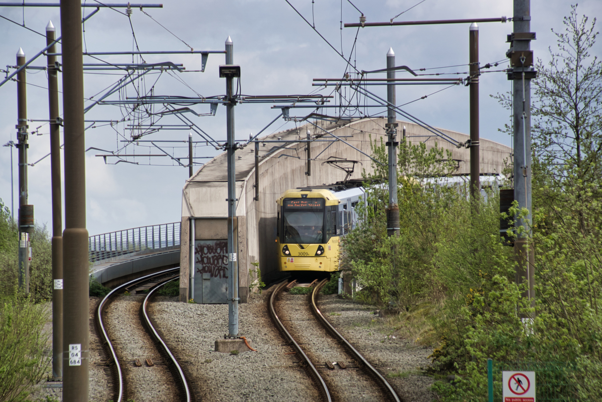
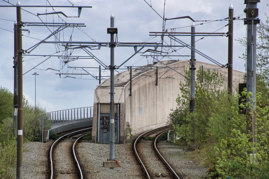
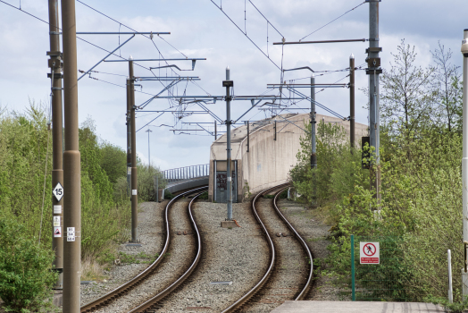
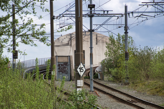
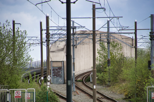
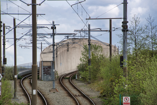
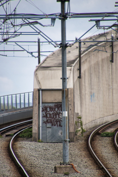
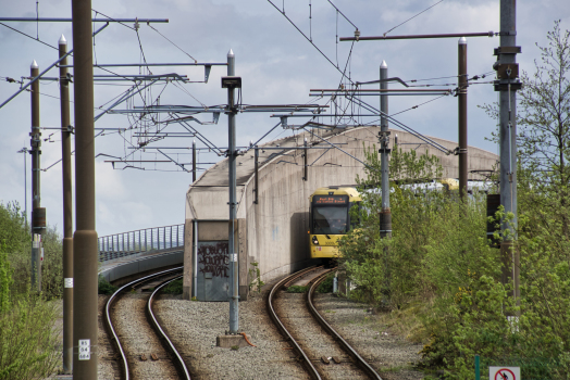
Tramway, light or metro rail bridge |
|---|---|
| Structure: |
Haunched girder bridge |
| Material: |
Prestressed concrete bridge |
| Support conditions: |
for registered users |
| Plan view: |
Structurae Plus/Pro - Subscribe Now! |
| Construction method: |
Rotation around a vertical axis |
| Material: |
Structurae Plus/Pro - Subscribe Now! |
Location
| Location: |
Manchester, Greater Manchester, North West England, England, United Kingdom |
|---|---|
| Part of: | |
| Coordinates: | 53° 30' 7" N 2° 11' 45" W |
Technical Information
Dimensions
| width | 10.25 m | |
| length | 131.8 m | |
| span lengths | 87.9 m - 43.9 m | |
| number of spans | 2 | |
| number of tracks | 2 | |
| track gauge | 1 435 mm | |
| abutments | number | 2 |
Design Loads
| design code(s) | BS 5400 Part 2 |
Materials
| deck |
prestressed concrete
|
|---|---|
| piers |
reinforced concrete
|
| abutments |
reinforced concrete
|
Participants
Design
Co-contractor
Prestressing

Relevant Web Sites
There currently are no relevant websites listed.
Relevant Publications
- (2010): Bridge Architecture + Design. 1st edition, Braun Publishing AG, Salenstein (Switzerland), ISBN 978-3-03768-025-4, pp. 258-261.
- (2007): Design and construction of the Metrolink Finback Bridge. In: Proceedings of the Institution of Civil Engineers - Bridge Engineering, v. 160, n. 2 (June 2007), pp. 71-79.
- Finback solution finds favour for light rail. In: Bridge Update, n. 46 (September 2004), pp. 4.
- About this
data sheet - Structure-ID
20014749 - Published on:
13/12/2004 - Last updated on:
17/04/2024
Structurae cooperates with


