
General Information
Project Type
| Function / usage: |
Electricity infrastructure building |
|---|---|
| Material: |
Concrete structure |
Location
| Location: |
Zwentendorf an der Donau, Lower Austria, Austria |
|---|---|
| Coordinates: | 48° 19' 46" N 15° 52' 48" E |
Technical Information
Dimensions
| width | 15.4 m | |
| height | 13.8 m | |
| length | 29.8 m | |
| wall thickness | 0.2 m |
Materials
| building structure |
reinforced concrete
|
|---|
Excerpt from Wikipedia
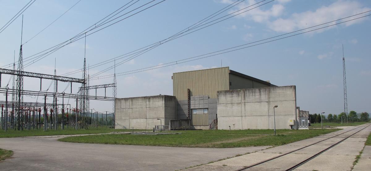
The GK Dürnrohr (German abbreviation for Gleichstromkurzkupplung Dürnrohr, in English meaning Dürnrohr HVDC-Back-to-Back Station) was a high-voltage direct current back-to-back scheme west of Dürnrohr substation, which was used for the energy exchange between Austria and Czechoslovakia between 1983 and 1996. The installation is no longer in use.
The GK Dürnrohr had a nominal transmission rating of 550 MW. The nominal value of the DC voltage in the intermediate circuit was 145 kV. The transmission losses of the facility were 1.4%.
History
Planning and construction
The planning of GK Dürnrohr was started in 1975, after a contract between Austria and Poland was agreed on concerning electric power exchange by a power line running over Czechoslovakia. Construction work at the facility started at the end of 1980. In the middle of 1983, the station started its service. After June 1983, the first experimental energy exchange with Czechoslovakia took place.
Decommissioning
After the synchronisation of electricity grids of West and Eastern Europe on 17 October 1995, the plant remained in operation until 31 October 1996, as Austria has no large 380 kV-grids, which is in contrast to Germany. However, afterwards in Poland, some[ weasel words] power stations were equipped with an efficient frequency regulation device; the power grids of the Czech Republic and Austria could be done interconnected directly without using a HVDC-interconnection. The high voltage switchgears were used in Vienna Southeast Substation and in Southern Burgenland, like the transformers, which had to be modified for a secondary voltage of 110 kV.
The obsolescence of the HVDC back-to-back station allowed an increase of the maximum power transmission rate between Dürnrohr and Slavětice to 1386 MW. By exchanging some coils of the PLC-facility, the transmission capacity could be increased to 1481 MW. The installation of the second 380 kV circuit on the pylons of the Dürnrohr-Slavětice powerline in 2008, for which they are already designed at time of construction, doubled this value to 2962 MVA.
The originally planned selling of the facility to Eastern Europe for an HVDC-back-to-back station never took place; such a transaction would have served as an interconnection between the power grids of Eastern Europe and former Soviet Union. In 2007, the remaining parts of the facility were dismantled. The valve hall is used today by the former operator Verbund AG for operational uses.
Rooms and equipment
Valve hall
The static inverter of the plant is situated in a reinforced concrete building that is 29.8 meters long, 15.4 meters large, and 13.8 meters high; at both long sides, there are two bays for the static inverter transformers. For protection against fire, the walls of the static inverter hall, which have a thickness of 20 centimetres, were equipped with stone wool insulation. The entire building is covered with a zinc-coated sheet, which serves as an electrical shielding and enclosure.
The static inverter hall also has a cellar, in which the air conditioning system, the water cooling system, and the water treatment plant are installed. At the western end to the narrow side of the static inverter hall, there is the equipment building. In the equipment building, there are battery and electric rectifier rooms, storage and test equipment rooms, and the ventilation devices for the air conditioning system, along with an auxiliary control room. A window consisting of three glasses, which cannot be opened, allows a view from the equipment building to the valves of the static inverter. At the eastern end to the narrow side, there is a smoothing coil.
Transformer
On both sides of the static inverter, there are two three-phase transformers, each dimensioned for a power of 335 MVA with a nominal winding ratio of 400 to 63.
Static inverter
The static inverter, which is implemented as a twelve-pulse inverter, uses for each valve function a serial switch of 44 thyristors with a maximum blockade voltage of 4.2 kV and a maximum nominal DC current rating of 3790 A. The total number of thyristors used in the facility is 1056. The thyristors had a wafer diameter of 100 mm during construction and were, at the time, the largest thyristors of the world.
Each static inverter consist of three thyristor towers, which are housed in the static inverter hall. Each thyristor tower contains a complete twelve-pulse branch of the static inverter. In these thyristor towers, for each valve function, four thyristor modules are used, which are arranged in two floors. Between the thyristor modules of a floor, there is a coil with an iron core. Parallel to the thyristor modules of a floor, there is a capacitor. Parallel to each valve function, there is a surge arrester in the form of a varistor.
Each thyristor module consists of a connection of 11 thyristors, to which there are parallel connections from a capacitaor and a resistor. The energy for the steering circuits of the thyristors is taken from the capacitor and resistor. As the thyristors and their steering electronics are on high voltage potential, the transmission of the ignition impulses from the control electronic on ground potential takes place via fibre optic cables. A second optical waveguide cable allows the transmission of data from the thyristor module to the main control electronics on ground potential. A programmable controller of the system SIMATIC S5 is used for controlling this system.
The thyristors and the coils switched with them are cooled with deionised water, which circulates in a closed cycle. The developed heat is delivered to a second cycle, in which there is a mixture of glycol and water. Over evaporation radiators, the heat of this cycle is transferred to the environment. For maintenance purposes, dedicated modules are exchanged against intact modules and carried in the repair and inspection room. For this, a telescope-lifting platform and a crane are installed in the static inverter hall.
Smoothing coil
At the eastern side of the static inverter hall, there is a smoothing coil with an iron core of 85 mH. It was built by the company ELIN and is, as the high-voltage transformers, oil-cooled.
AC filters
As AC-fiters, four resonance circuits are installed on both sides of the plant. Each of the filters consist of a series-connection of a two-microfarad capacitator with a coil to which a 615 ohm resistor is parallelized. One filter on each side uses a 41 mH air-core coil, while the other has a 29 mH air-core coil. On each power exit, there is also a bank of capacitors for reactive power compensation. The capacitors' values are two microfarads for the exit of the line toward Czech Republic and one microfarad for the exit toward Austria.
SVC-Compensator
The SVC-facility remained in service after the shut-down of the HVDC back-to-back station. It consists of two groups of single-phase coils with an inductivity of 86 mH, which are fed via a tertiary winding on the 380 kV/220 kV-transformers with a voltage of 30 kV and which can deliver a maximum reactive power of 200 MVar. The first coil group went into service in 1982, the second in 1986.
Power line to Czech Republic
The 102-kilometre (63 mi) long powerline to Slavětice substation in Czech Republic is a double-circuit 380 kV-line. However the second circuit was installed in 2008. In the Czech Republic, two-level conductor arrangement is used, while in Austria three-level conductor arrangement is used. The line crosses the border near Kleinhaugsdorf. When built, it was the first electrical power interconnection between the synchronous grid of Continental Europe and the Interconnected Power System of the Eastern block. In 1986 Robert Ospald succeeded the escape to Austria over the ground conductor of this line.
Text imported from Wikipedia article "GK Dürnrohr" and modified on July 23, 2019 according to the CC-BY-SA 4.0 International license.
Participants
Currently there is no information available about persons or companies having participated in this project.
Relevant Web Sites

- About this
data sheet - Structure-ID
20042092 - Published on:
29/12/2008 - Last updated on:
02/01/2018


