
General Information
| Status: | in use |
|---|
Project Type
| Material: |
Prestressed concrete bridge |
|---|---|
| Plan view: |
Structurae Plus/Pro - Subscribe Now! |
| Function / usage: |
Motorway bridge / freeway bridge |
| Structure: |
Box girder bridge |
| Support conditions: |
for registered users |
| Construction method: |
Precast girders with cast-in-situ slab |
| Structure: |
Haunched girder bridge |
| Material: |
Structurae Plus/Pro - Subscribe Now! |
Location
Technical Information
Dimensions
| main span | 56.227 m | |
| total length | 560.4 m | |
| span lengths | 20.484 m - 32.627 m - 35.196 m - 38.243 m - 56.227 m - 32.727 m - 36.674 m - 38.669 m - 29.466 m - 28.869 m - 36.507 m - 29.437 m - 29.431 m - 32.914 m - 32.924 m - 30.045 m - 19.972 m | |
| number of spans | 17 | |
| deck | deck width | 10.7 m |
| girder depth | 1.70 - 2.55 m |
Materials
| superstructure |
prestressed concrete
|
|---|---|
| piers |
reinforced concrete
|
| abutments |
reinforced concrete
|
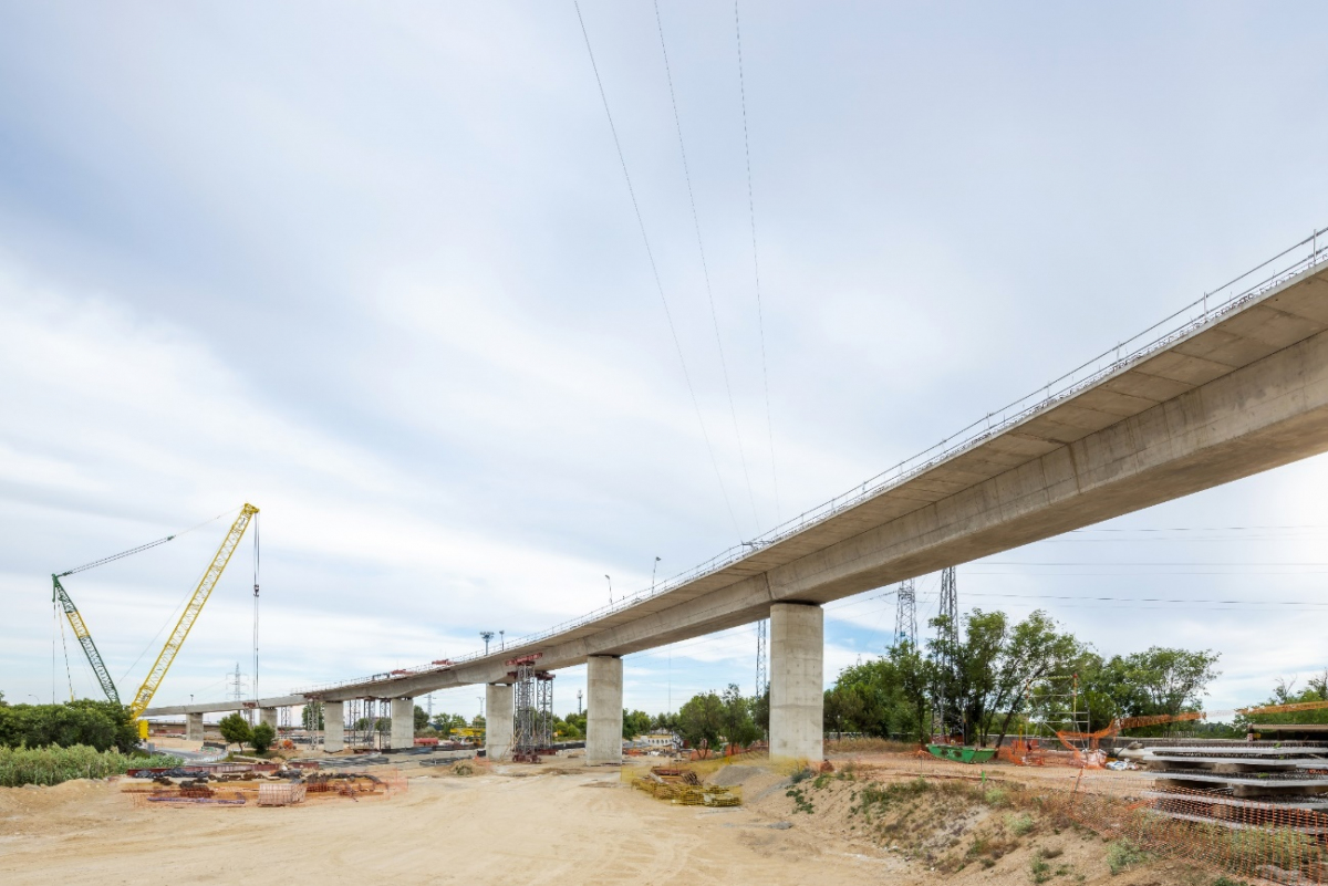
Viaduct for the link at M-40 ring road in Madrid (Spain)
The old existing concrete viaduct at the link between M-40 ring road and the expressway to Colmenar in Madrid (Spain) was subjected to a very comprehensive and thorough process of evaluation and testing after high deck deflections and surface cracking were detected. As conclusion of these studies very severe damages and a process of concrete degradations were confirmed which lead to the decision of dismounting the existing deck structure and constructing a new one supported on the existing substructure which, in turn, had to be also repaired and reinforced.
Grupo Puentes carried out both the process of deck disassembly and the construction of the new deck to replace the old one in the record time of approximately nine months.
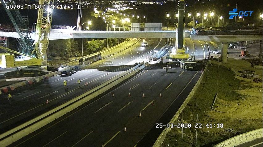
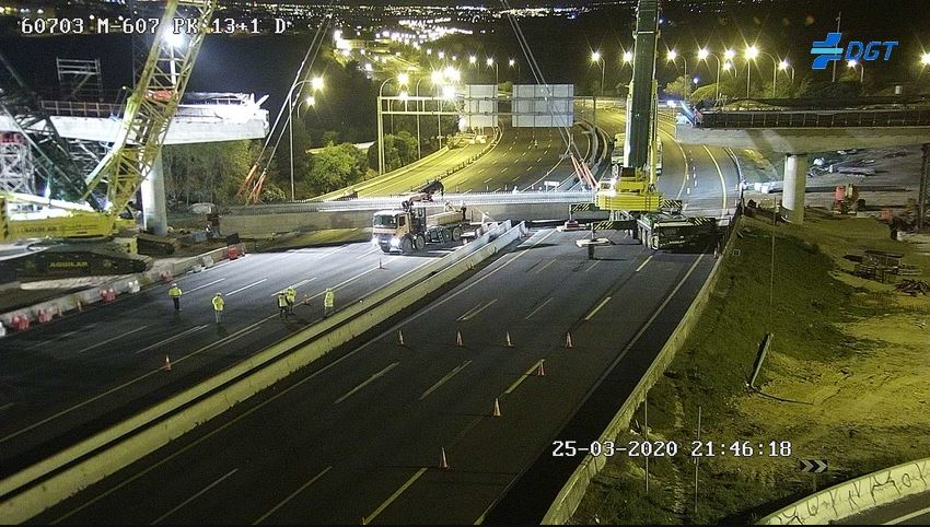
It is important to emphasize that the viaduct is located in a very traffic congested link to approach Madrid from the North and, due to this fact, the social impact of this process, demolition-reconstruction, had to be considered carefully. Another important fact to take into account was that the viaduct crosses over several roads, not only the main ones, M-40 ring road and Colmenar expressway, but also two approach ramps and two railway lines, one of them a high-speed rail line.
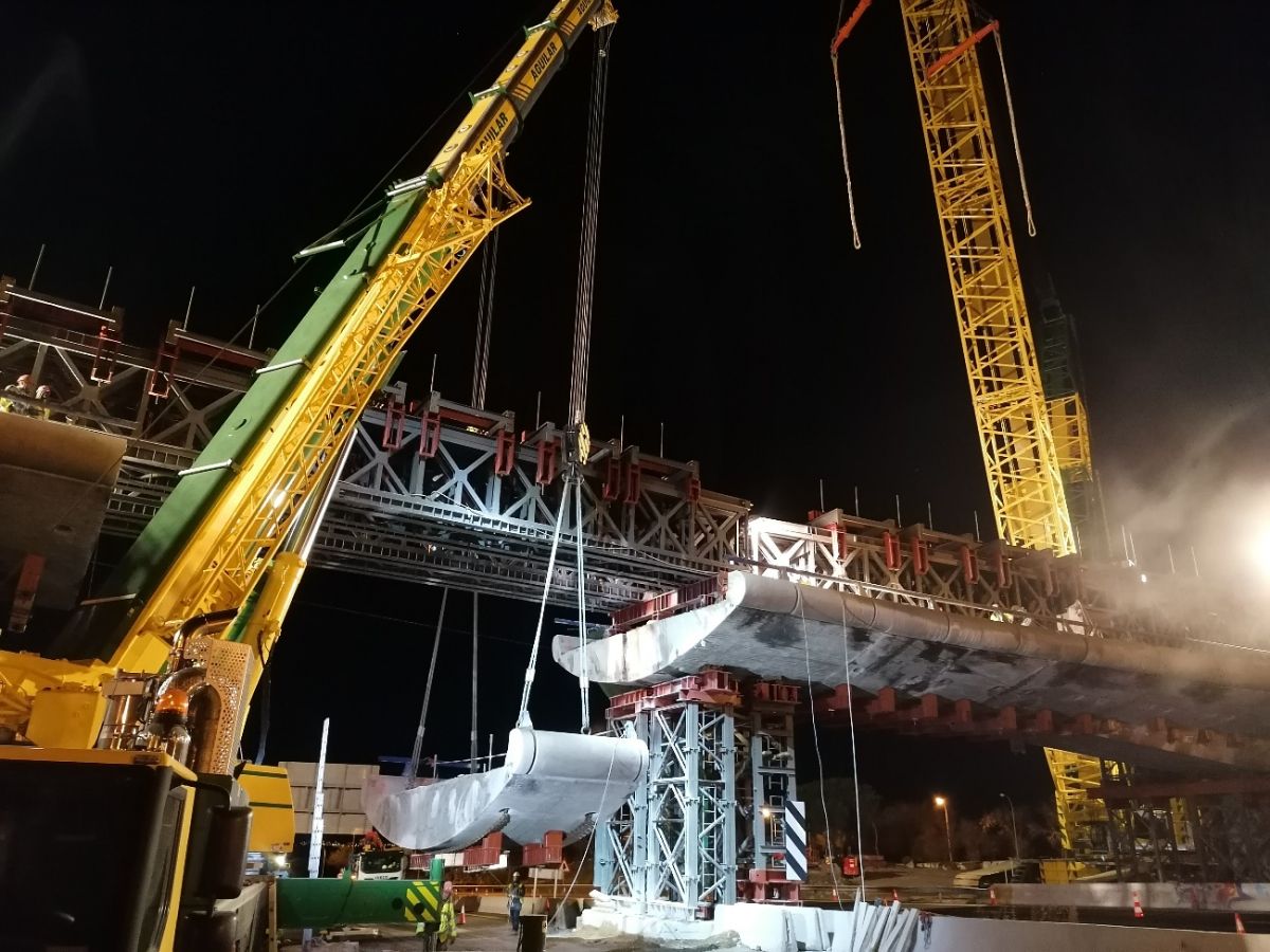
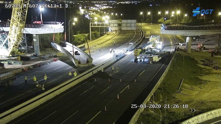
The process of disassembly of the old deck has been performed by means of cutting completely the sections with diamond wire, which has advantages from the point of view of safety and control of the structural behavior of the bridge. In this way, the deck was divided into sections of variable lengths which, after being supported on temporary structures, were taken away by means of cranes to the demolition area. The cutting order and the corresponding procedures have been carefully studied to ensure the stability and integrity of the structure and to avoid at all times the complete traffic cutting of the roads under the bridge.
The phase of disassembly of the span over the M-40 ring road was particularly difficult and hazardous due to the span length, the longest one (56.227 m). For this phase, and to ensure safety during all operations, steel trusses were placed over the deck spanning each carriageway of the M-40 ring road. These trusses were supported on the existing substructure and on temporary towers to allow that the deck sections were hanged from the trusses once they had been cut. The deck sections were taken away by cranes and trucks during the night cutting only the traffic on one of the carriageways of the M-40 each time.
The main constraint for the new viaduct deck was to keep the same alignment and span lengths as the old one since the original piers and foundations are also kept with only some rehabilitations works. Therefore, to comply with all these conditions the viaduct has been designed as a continuous deck with 17 spans, a total length of 560.4 m, and variable span lengths, with a maximum value of 56.227 m, over the M-40 ring road. The span length distribution is: 20.484 + 32.627 + 35.196 + 38.243 + 56.227 + 32.727 + 36.674 + 38.669 + 29.466 + 28.869 + 36.507 + 29.437 + 29.431 + 32.914 + 32.924 + 30.045 + 19.972 m.
The deck section consists of a U precast post-tensioned beam curved in plan and a top concrete slab cast over thin precast slabs. The total deck is composed by 22 U beams fully connected along the deck by means of prestressing bars and tendons in such a way to achieve a continuous deck along all the length of the viaduct. The depth of the precast beams is, in general, constant of 1,70 m for most of the spans but it is increased linearly up to 2.55 m at the piers located close to the longer spans (P-4, P-5, P-7, P-10 y P-11). The deck is 10.7 m wide to carry two lanes with hard shoulders and edge barriers.
Due to the specificity of this kind of modular bridge and the necessity of minimizing the traffic cutting on the roads crossing under the viaduct, the erection process for the beams has been very carefully studied and executed, with full control of all the movements which has allowed to place the beams at their positions with very reduces tolerances to provide continuity to the deck. During this erection process, ancillary structures together with temporary bearings have been used to support some of the beams previously to the connections between them. Other beams have been temporarily supported on the adjacent ones without ancillary structures. It must be outlined that the beams over the railway lines were placed in position during two consecutive nights, only three hours per night, without railway traffic disruption.
Participants
Relevant Web Sites
There currently are no relevant websites listed.
- About this
data sheet - Structure-ID
20081758 - Published on:
03/10/2021 - Last updated on:
03/10/2021


