
General Information
| Completion: | 2012 |
|---|---|
| Status: | completed |
Project Type
| Function / usage: |
Railroad (railway) bridge |
|---|---|
| Structure: |
Rigid frame bridge |
| Support conditions: |
for registered users |
| Material: |
Reinforced concrete bridge Structurae Plus/Pro - Subscribe Now! |
Awards and Distinctions
| 2015 |
entry
for registered users |
|---|
Location
| Location: |
Spital am Pyhrn, Upper Austria, Austria |
|---|---|
| Coordinates: | 47° 39' 50.75" N 14° 20' 51.11" E |
Technical Information
Dimensions
| span lengths | 16.50 m - 22.00 m - 29.00 m - 21.50 m | |
| number of spans | 4 | |
| horizontal radius of curvature | 270 m |
Materials
| deck |
reinforced concrete
|
|---|---|
| piers |
reinforced concrete
reinforced concrete |
| abutments |
reinforced concrete
|
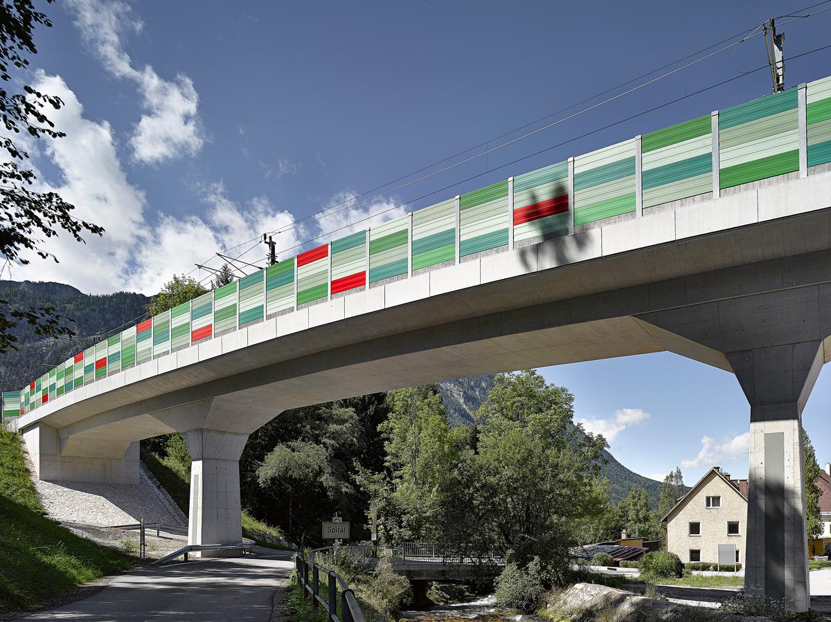
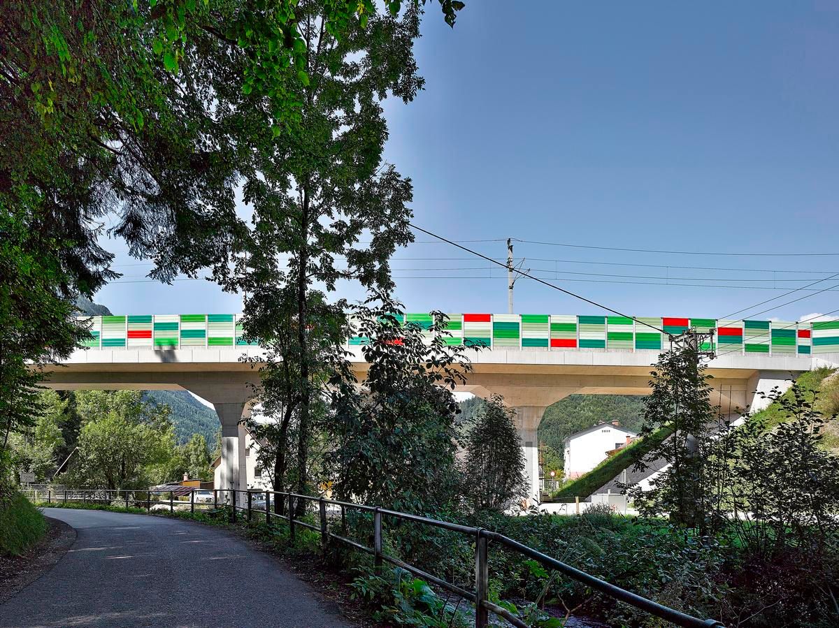
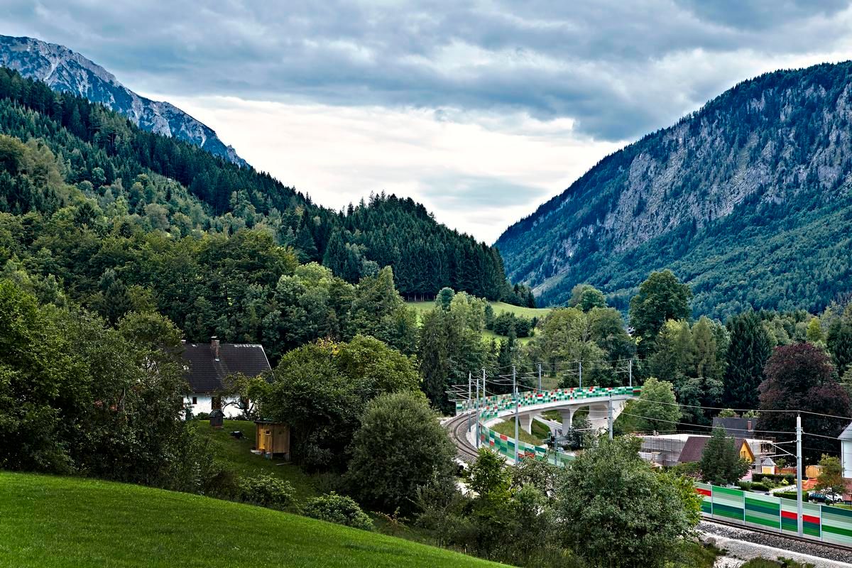
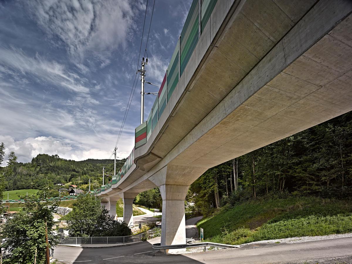
Replacement of the Trattenbach Bridge in Spital am Pyhrn
The railroad bridge over the Trattenbach represents a novelty for modern civil engineering. It is an integral structure with monolithic restrained abutments. This design allows the bridge to be very slender and fits well into the valley of the Trattenbach gorge. The loads from traffic, especially the horizontal loads, are transferred very economically by the chosen system. As the first railroad structure in Austria, the bridge was calculated completely in accordance with Eurocode and verified by monitoring with trial loads before traffic was transferred.
The Austrian Federal Railways expect savings of at least 15% over the entire life cycle compared to conventional construction methods that do not include a frame-like structure.
Task statement
The single-track, electrified railroad line from Linz to Selzthal is transferred over the valley incision of the Trattenbach in Spittal am Phyrn. The old supporting structure consisted of brick arches with stamped concrete. The river field was bridged by means of a directly driven steel truss with a span of 40 meters. The condition of the bridge, which was over a hundred years old, required a completely new structure.
In this course, several variants of the new bridge were designed in a preliminary planning. As variants were worked out:
- A monolithic frame of reinforced concrete with tied-in abutments over four spans
- .
- A composite bridge over three spans
- .
- A three-span bridge with fish-bellied girders as a composite structure in the river field
- .
- A prestressed concrete bridge as a continuous girder with four spans
In an evaluation of the variants, which took into account not only the construction costs but also the costs during the service life, the reinforced concrete frame over four spans turned out to be the most sophisticated solution in terms of design and at the same time the most economical over the life cycle.
The construction of the bridge was helped by the fact that the new construction improved the alignment. The radius of 250 m in the existing bridge was increased to 270 m for the new construction. The new bridge could be built next to the existing bridge.
Description of the structural system
The client's choice of the bridge variant was the monolithic frame construction. This construction was used for the first time in the network of the Austrian Federal Railways with a total length of 100m. On the part of the client, this decision broke new ground.
The main reasons for the decision were the low maintenance load that can be expected with a frame structure and the massive superstructure, which considerably reduces the noise immission from the nearby residential area.
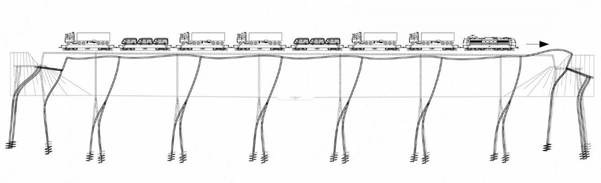
The piers of the bridge as well as the abutments tie monolithically into the superstructure. The piers are founded on two rows of drilled piles (diameter 1.50 m). The abutments are also deeply founded. The great advantage of this design is the favorable transfer of the high braking loads from rail traffic. In continuous girder systems resting on bearings, the horizontal forces are transferred to the comparatively stiff abutments via the longitudinal restraints. This necessitates elaborate restraint structures as well as expensive foundation structures. The monolithic design distributes the braking forces of the railroad evenly between abutments and piers because the restraint of the substructures into the superstructure creates a very stiff trestle effect. The horizontal forces could be transferred where very economically. This is clearly shown by the deformation figure in Figure 1.

Figure 1: Frame bridge with monolithic restrained abutments under braking load
The bridge was the first structure for the Austrian Federal Railways to be calculated according to the then newly introduced Eurocodes. For the verification of the deformations as well as the fatigue loading, haunches towards the supports and abutments were necessary. The haunches were stepped harmoniously to the pier over the height. At the transition to the embankment area, a trailing slab is placed, which rests on a lean concrete wedge. This design prevents settlements and compensates for horizontal movements from temperature and braking loads. The calculated deformation at the transition to the embankment was limited to 5 mm.
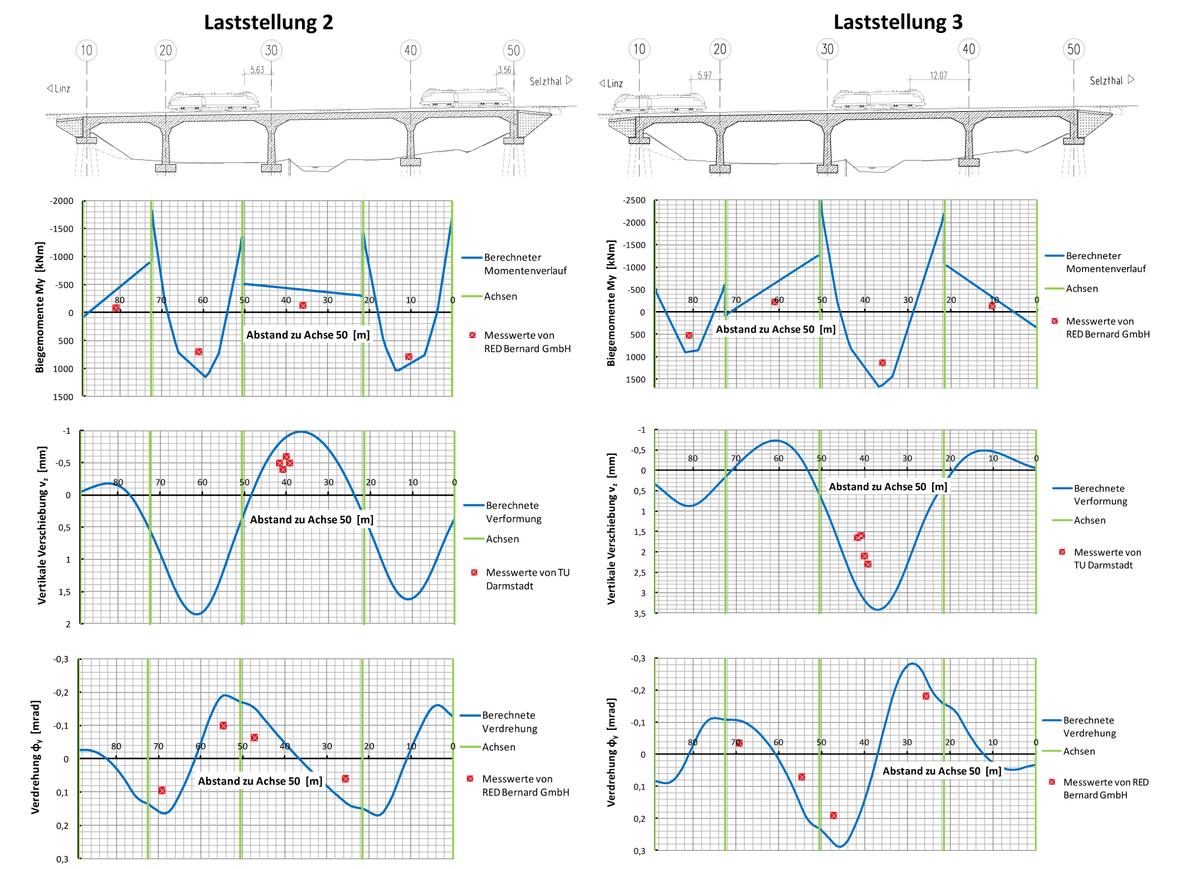
To ensure the assumptions in the stability verifications, a trial load with deformation measurements was carried out on the part of the client. Four diesel locomotives, each weighing 88t, were used for the measurements. Static loads, dynamic overruns and braking runs were used to compare the calculated deformations and settlements with the measured values. This resulted in significantly lower measured values, which were in the range of 1/10 to a maximum of 1/5 compared to the theoretical values (for this, see Figure 2).

Figure 2: Excerpt from the results report on the deformation measurements at the test load
Choice of construction materials
The bridge is carried with four spans over the relatively narrow valley incision and the spans are comparatively small with a maximum of 29.00 m in the middle span. The choice of material fell on „simple“ reinforced concrete for these edge conditions. A reinforced concrete bridge can be designed with slendernesses of 29.00/1.30 = 22 and 29.00/2.55 = 11 under the necessary deformation constraint. Prestressing the concrete would increase the horizontal deformation paths for the Trattenbach Bridge, requiring additional rail extensions.
The following construction materials were used:
- Superstructure: C35/45
- Abutment: C30/37
- Pillars: C35/45
- Pile head beams: C30/37
- Bored piles: C30/37
- Reinforcement steel: BST 550, high ductility
Design notes
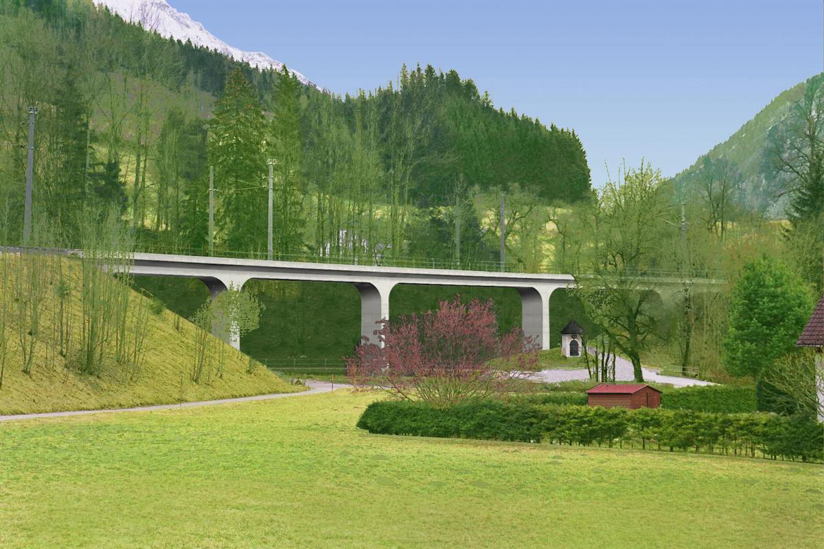
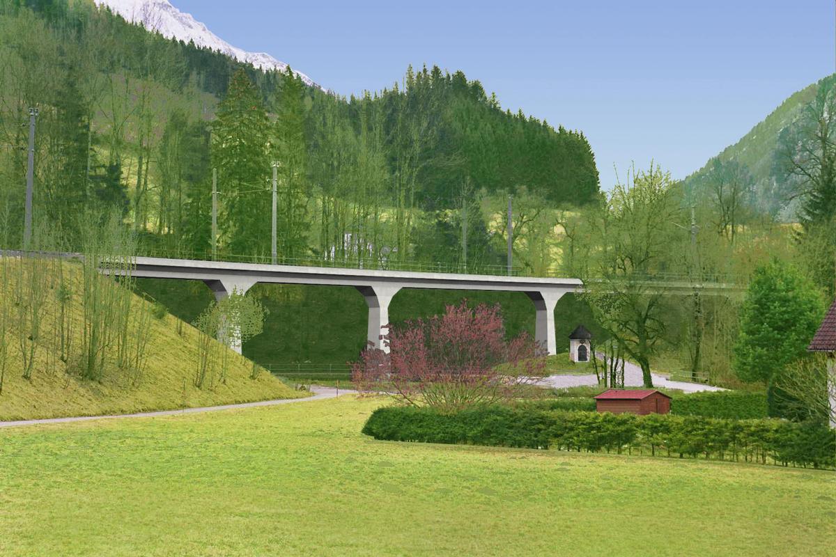
The gentle, relatively narrow valley of the Trattenbach is crossed by the railroad line coming out of a tunnel in an arc. The radius lends a certain tension to the widening valley. The valley incision is responded to with variable spans. For the frame bridge, the spans are 16.50+22.00+29.00+21.50 = 89 m. The ratio between the opening width between the substructures and the clear height in the span is almost the same for all spans, so that the bridge fits very homogeneously into the valley incision. The river field is emphasized by the largest span. A horizontal offset of 5 cm between the lower edge of the superstructure and the upper edge of the piers in the transverse direction creates a visual continuous effect of the superstructure along the entire length of the bridge. Two variants were investigated for the design (see Figure 3). Straight coving twice stepped and a coving in the form of a circular radius. Due to the clearer shape and easier fabrication of the haunches, the frame bridge was designed with straight haunches.


Figure 3: Visualization of the variants with polygonal haunches (top) and radial haunches (bottom)
Explanatory report by SSF Ingenieure AG for submission to the Ulrich Finsterwalder Ingenieurbaupreis 2015
Participants

Relevant Web Sites
There currently are no relevant websites listed.
- About this
data sheet - Structure-ID
20066625 - Published on:
01/12/2014 - Last updated on:
02/01/2018


