
General Information
| Other name(s): | Pasarela de Mato Grande |
|---|---|
| Status: | in use |
Project Type
| Structure: |
Cable-stayed bridge with fan system |
|---|---|
| Function / usage: |
Pedestrian bridge (footbridge) |
| Material: |
Steel-reinforced concrete composite bridge |
| Secondary structure(s): |
Structurae Plus/Pro - Subscribe Now! |
| Material: |
Structurae Plus/Pro - Subscribe Now! Structurae Plus/Pro - Subscribe Now! |
| Secondary structure(s): |
Structurae Plus/Pro - Subscribe Now! |
Location
| Location: |
La Coruña, La Coruña, Galicia, Spain |
|---|---|
| Address: | Avenida San Cristobal |
| Coordinates: | 43° 20' 33.65" N 8° 24' 19.93" W |
Technical Information
Dimensions
| main span | 39 m | |
| total length | 159 m | |
| deck | deck slab thickness | 6 cm |
| pylon | height | 20 m |
Materials
| pylon |
reinforced concrete
|
|---|---|
| piers |
reinforced concrete
|
| foundations |
reinforced concrete
|
| girder |
steel
|
| deck slab |
reinforced concrete
|
Structural Description
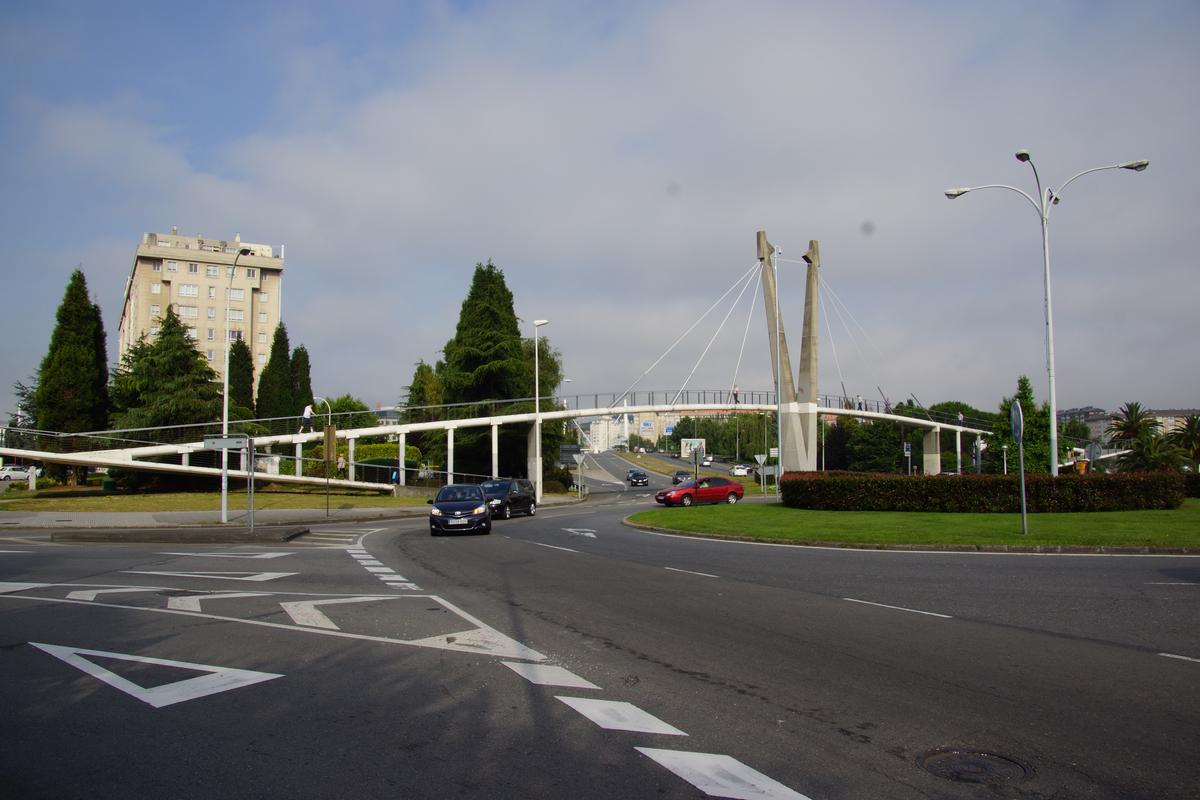
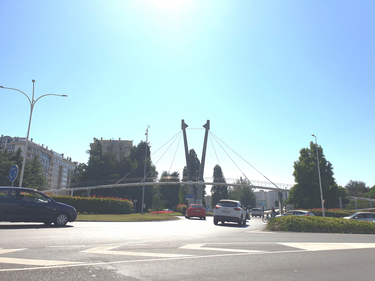
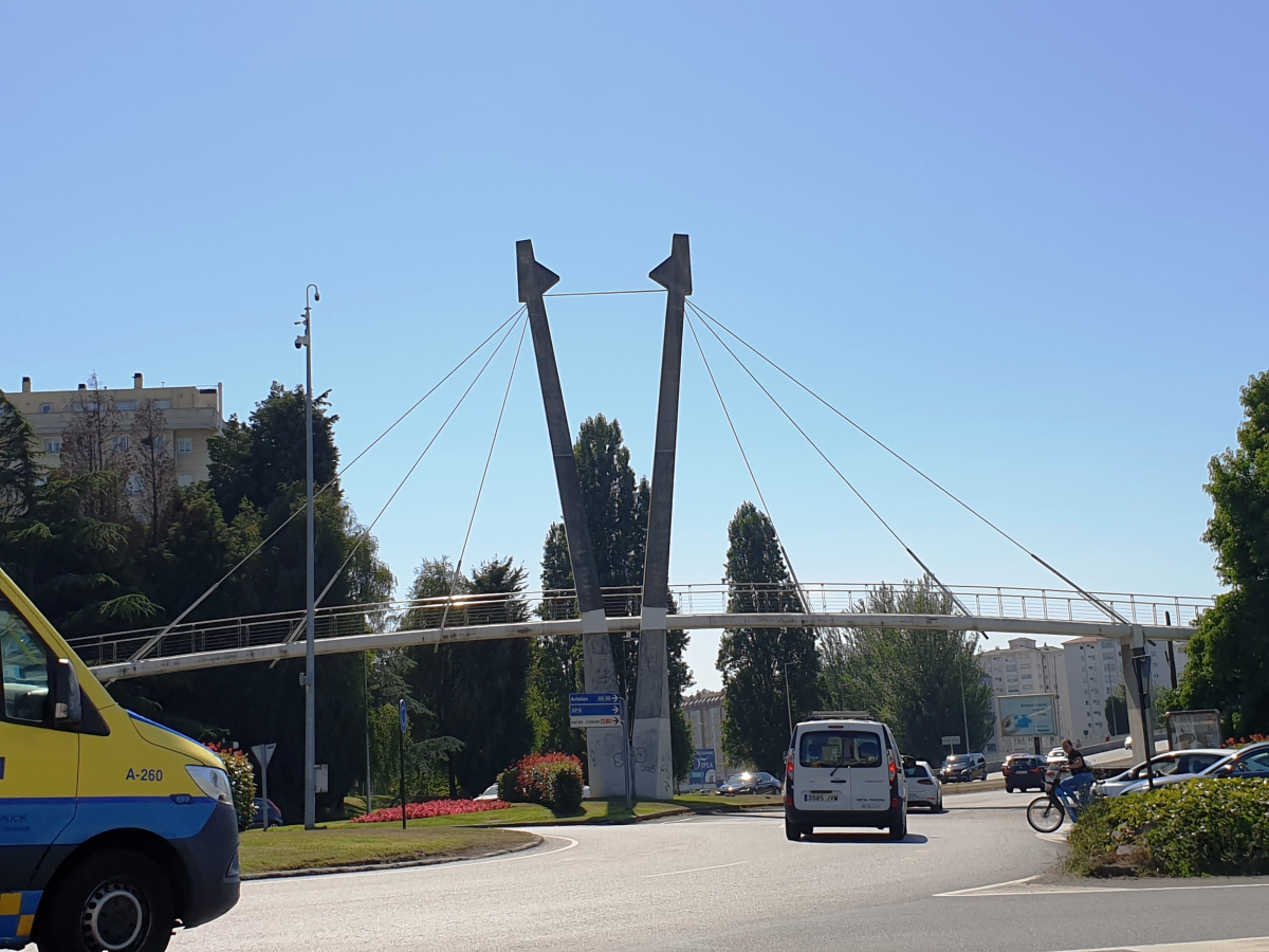
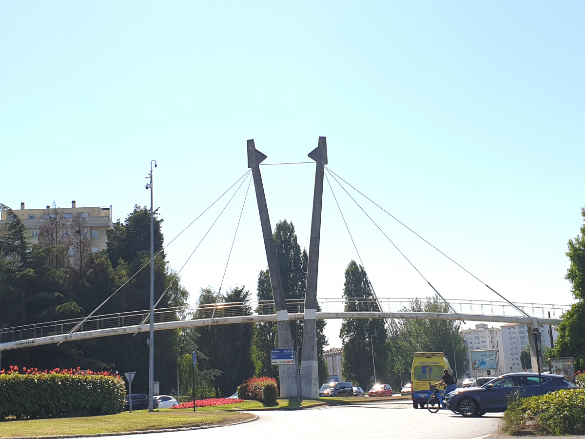
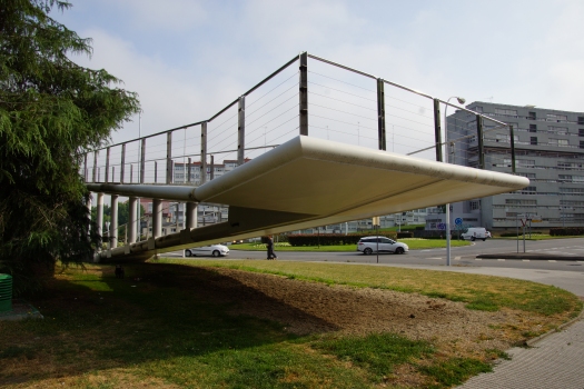
The footbridge, called the "sailboat", has a straight steel deck and the concrete piles. The center spans are suspended from a set of eccentric stays while the access ramps are designed as cantilevers. These cantilevers were necessary as the structure could not be supported by the soil.
The footbridge has a clear span of 39 meters in a straight line, to which two steel cantilevering ramps are added with a span of 27 meters on one side and 24 meters on the opposite side. The clear span has a parabolic elevation and a rise-to-span ratio of 1 to 37. The design of the ramps, which is the most significant element, is zigzag-shaped, with a 10 percent gradient. The ramps are linked to one another by vertical tubular transoms, and thus constitute a Vierendel beam with a linearly variable depth with a maximum value of 5,50 meters.
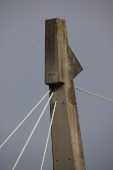
The pylon was designed as a very stiff V-shaped pylon 20 meters in height in reinforced concrete. The two piers adjoining the suspended spans are also designed in reinforced concrete. The asymmetric main span of the footbridge is suspended from the center pylon at a height of 18 meters by 6 ties, 3 ties on each side. The ties are of two or three 0.6" strands. The pylon head has a horizontal tie consisting of four strands that link the two pylon braces on the top. The suspension is eccentric to the deck.
The steel deck cross-section was designed with a plane wing profile, measuring 3,00 meters in width and topped by two semicircles of 40 and 20 centimeters in diameter. This makes it appear very light. The walkway is formed by a structural concrete slab of 6 centimeters thick and 2,40 meters wide, linked to the deck top plate, with a metallic profile. The rough concrete surface was chosen deliberately to avoid sliding during frost or rain and dynamic effects that could be the result of the pedestrian passage. The steel deck cross-section is divided into inner cells by a set of longitudinal diaphragms to achieve constant torsion. Besides, cross diaphragms and medium stiffenings were designed to avoid buckling in the lower plate. The structural concrete avoids that the upper sheet gets dented too.
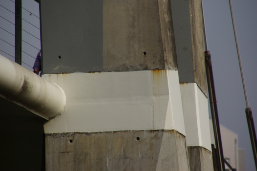
The ramps compensate torsional effects from bending action on the vertical tubular transoms. The cantilever ramps generate significant traction over the board and nearly horizontal compression forces in the foundation. The imbalances resulting from overloading on one side of the central pylon are absorbed by bending in the pylon which was designed with very stiffness.
As the most important actions are vertical, the resultant of the horizontal forces in the foundation is zero. This is the reason why only one foundation was designed for the footbridge and it was analyzed as a freely-supported beam, resting on piles of 45 centimeters in diameter, 650 kN of permissible load, inserted in the lower resistant soil that consists of a degraded rock and decomposed granite. The foundation cross-section is rectangular, and measures 1.20 m in width and is 1.80 m in depth. The foundations become wider in the central pylon base, with a geometry of 4.80 by 5.50 by 1.80 meters, and on the two end pier bases, which have a geometry that is difficult to describe and it is conditioned by the piers.
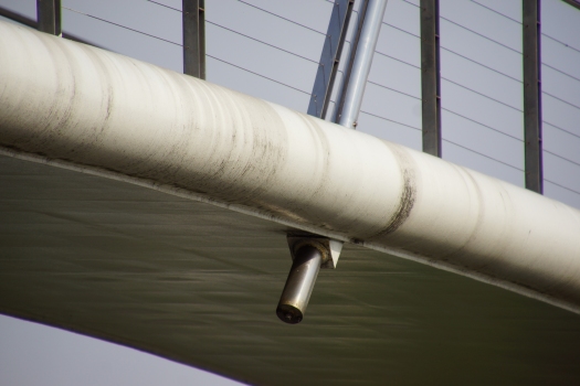
The guardrail has been designed using very light stainless steel so that it does not distract from the structure itself. It consists of a tube measuring 43 millimeters in diameter, linked by a plate with the vertical elements composed of two parallel plates stiffened by stainless steel sheets. The transoms are linked by five stainless steel wires measuring 3 millimeters in diameter.
Participants
- Antonio González Serrano (designer)
- Julio Besiga Díaz Blanco (architect)

Relevant Web Sites
There currently are no relevant websites listed.
Relevant Publications
- (2001): Pasarela atirantada "El Velero", en La Coruña. A stayed footbridge in La Coruña, Spain. In: Informes de la Construcción, v. 53, n. 473 (June 2001), pp. 5-9.
- About this
data sheet - Structure-ID
20012254 - Published on:
09/06/2004 - Last updated on:
11/09/2024


