
General Information
Project Type
| Material: |
Reinforced concrete structure |
|---|---|
| Structure: |
roof: Gridshell roof: Membrane structure building structure: Frame |
Awards and Distinctions
| 2015 |
entry
for registered users |
|---|
Location
| Location: |
Bochum, North Rhine-Westphalia, Germany |
|---|---|
| Address: | Querenburger Str. 45 |
| Coordinates: | 51° 28' 4.47" N 7° 13' 52.06" E |
Technical Information
Dimensions
| width | ca. 70 m | |
| height | ca. 12 m | |
| length | ca. 125 m | |
| gross floor area | 13 435 m² |
Cost
| cost of construction | ca. Euro 31 600 000 |
Materials
| membrane |
ETFE foil
|
|---|---|
| building structure |
reinforced concrete
|
| shell |
steel
|
New Bochum High School
Task definition
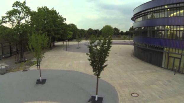
The city of Bochum planned to merge two high schools into one structure at the existing site with subsequent demolition of the existing buildings. The new building was to convey an open and free atmosphere and blend harmoniously with the natural monument of the Geological Garden in the existing planning area. At the same time, emphasis was placed on preserving the district's east-west connection for pedestrians and cyclists.
Description of the construction
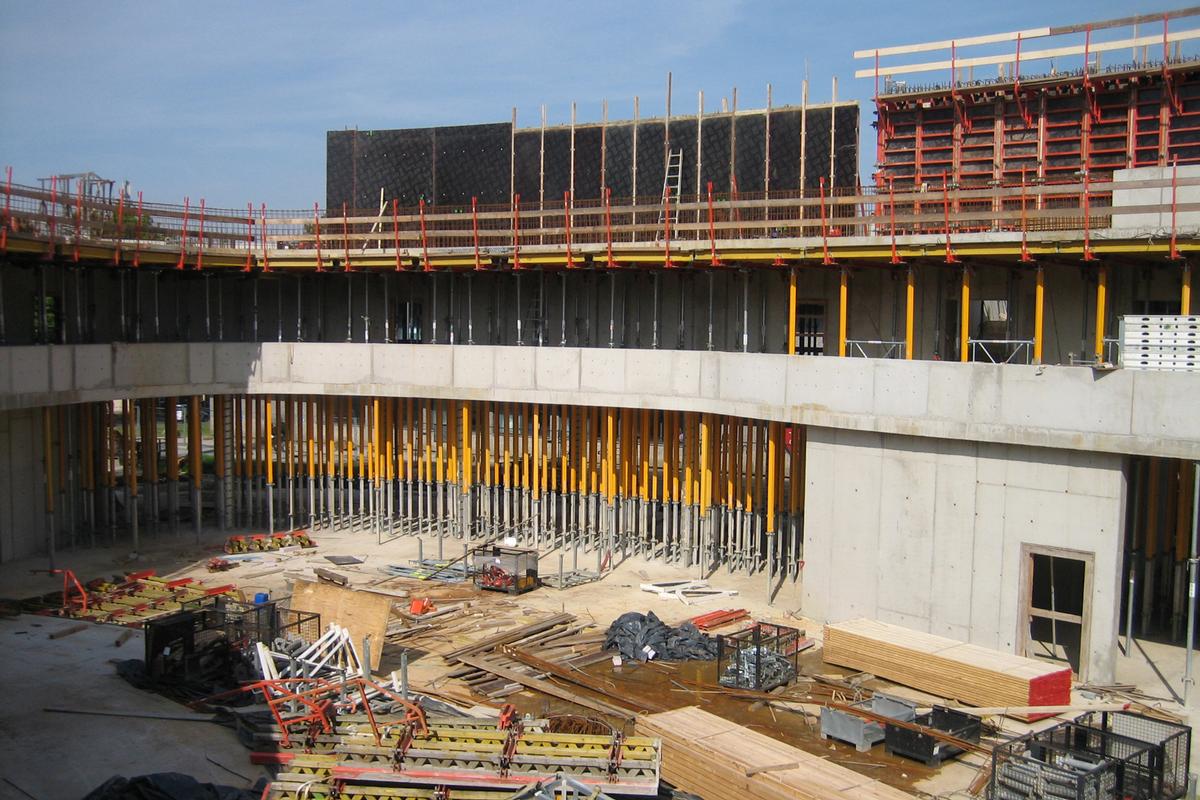
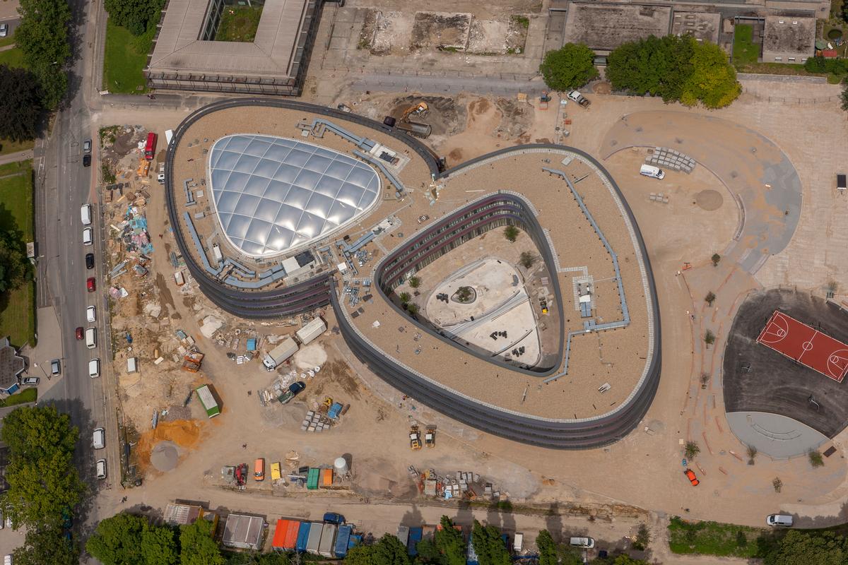
The three-story high school with floor plan dimensions of approximately 125 x 70 m and a height of approximately 12 m was constructed as a reinforced concrete skeleton structure. The floor plan geometry results from two abutting rings with circumferentially variable radii.
The entire building is designed as a jointless monolithic structure in cast-in-place concrete. The reinforced concrete flat slabs with a thickness of 30 cm are supported along the facade and the corridor partitions by circular columns or rectangular columns integrated into the walls. The distances between the columns are usually approx. 7-8 m. In addition, the slabs rest on the bracing stairwell, elevator and fire walls.
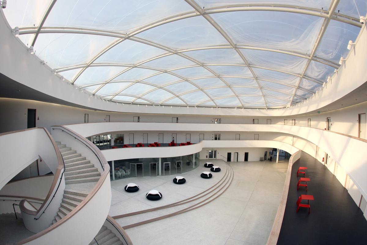
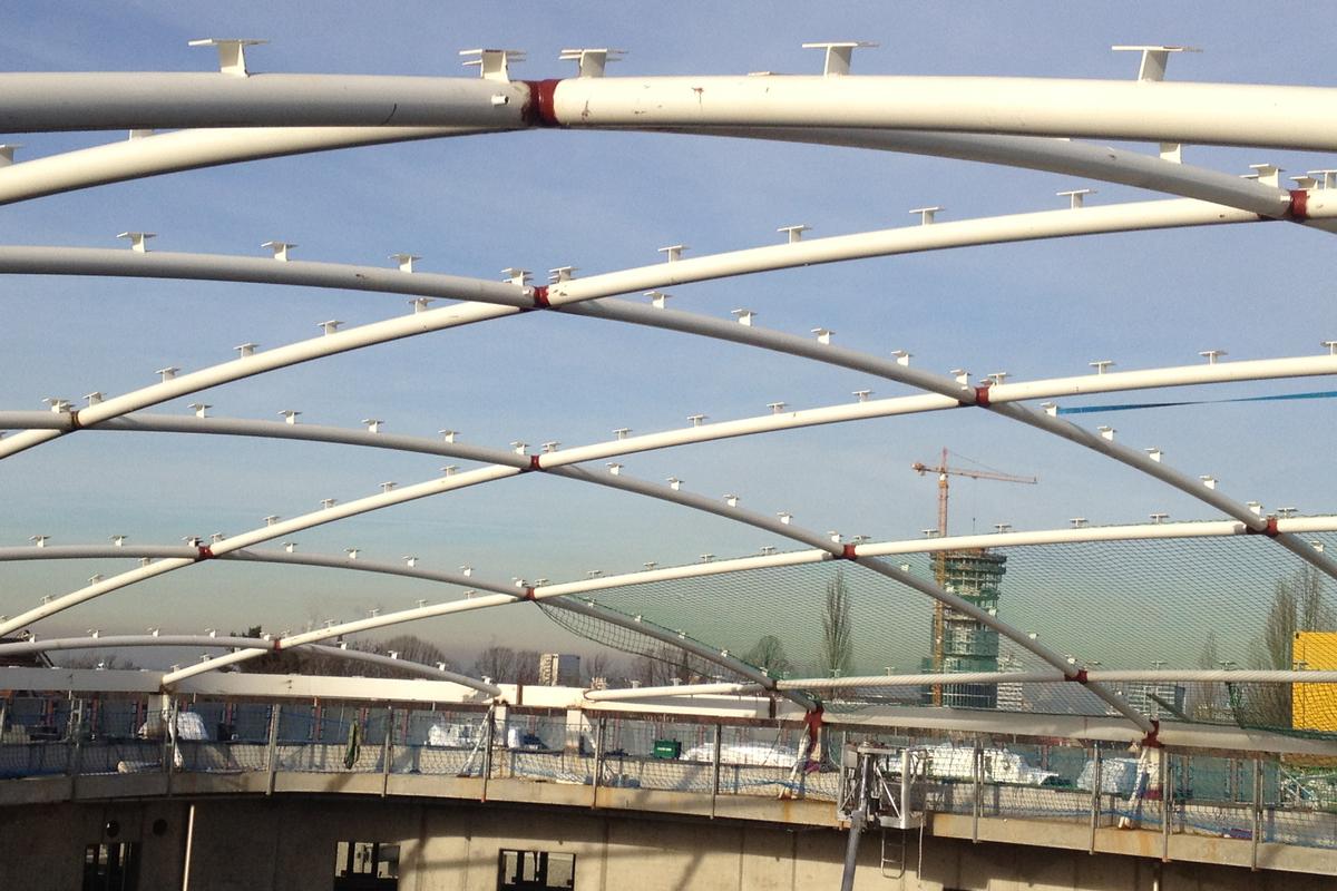
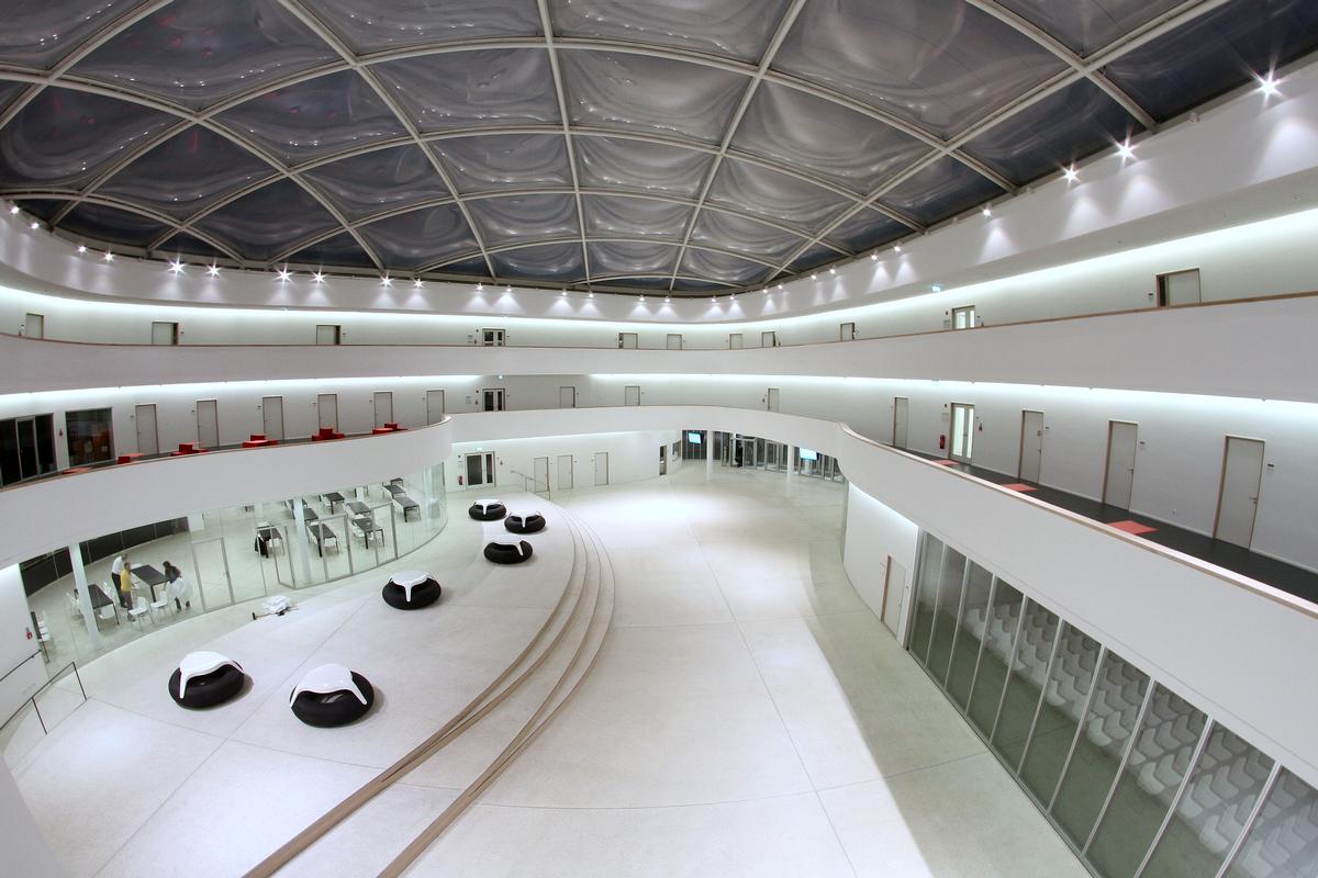
The atrium in the Westring is lit from above via a transparent roof dome. Designed as a three-layer, pneumatically supported foil cushion roof, the roof structure presents itself as a light and filigree steel construction. Arched hollow steel sections with a diameter of only 152 mm and wall thicknesses of 8 to 12.5 mm span the approx. 1,000 m² roof.
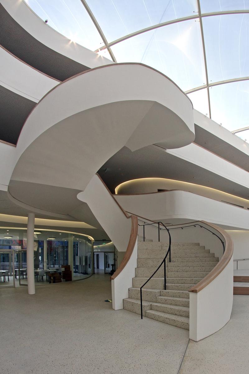
A sculpturally shaped staircase, also in reinforced concrete construction, was chosen as the central element for access to the upper levels from the atrium hall.
Choice of construction materials
The reinforced concrete skeleton structure of the building was made as an in-situ concrete structure of C30/37 and, in areas subject to higher compressive stresses, of C45/55 in conjunction with BSt 500A reinforcing steel.
The filigree steel structure for the ETFE cushion roof was manufactured in structural steel S355.
The cushion structure consists of three layers of ethylene tetrafluoroethylene films with thicknesses of 250 µm for the outer films and 80 µm for the inner film layer. Modulus of elasticity Ef,23°= 700 N/mm², tensile strength σf,23°= 40 N/mm² , Poisson's ratio µf,23° = 0.40 - 0.45, clamping profiles in aluminum.
Special engineering
The structural engineering work was characterized by the following main topics: Organic geometry, column-free auditorium or entrance hall on the first floor, sculptural staircase, roof structure covered with ETFE cushions.
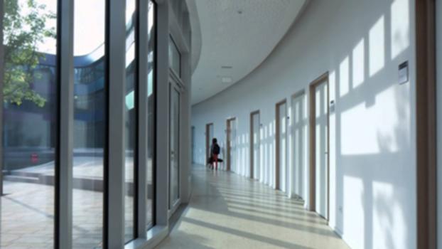
In the reinforced concrete structure, curved walls and wall beams, rounded ceiling edges, load-bearing and non-load-bearing parapets, and rounded stairs and landings are the dominant structural elements. The organic geometry resulted in continuous influences and dependencies on formwork, reinforcement, built-in components, steel structures and finishing, which had to be consistently and meticulously planned through in order to always preserve all boundary conditions.
The architect's design envisaged a completely column-free assembly hall on the ground floor. In addition, there was to be the possibility of being able to create a flowing transition to the hall. This resulted in the need to bridge a span of 26 meters. To make this possible, the walls on the two levels above, E1 and E2, were designed as wall-like girders so that, together with the slabs, a very efficient load-bearing system was created. The slabs perform the function of bracing sheaves against the horizontal shear generated by the curved wall shape.
The structural design of the wall girder became a challenge due to the irregularly arranged door openings on both levels. For the 45-cm-thick girder, a truss construction over two levels was chosen as the structural system, with the truss struts routed around each of the doors. The floor slabs form the tension and compression chords. The wall girder bears on the stair core 1 and a support b/d= 70/45 cm next to the stage of the auditorium, which is twisted with respect to the axis of the girder.
The reinforcement of the truss struts was designed to run diagonally in the plane of the wall, according to their inclination. The concentrated reinforcement strands had to be routed with different curvatures over two levels and anchored in the uppermost and lowermost slabs via built-in components. Orthogonally to this, the connecting and supporting reinforcement of the slab, as well as the connection to the tension bands stored in the slabs, were threaded through The planning of the reinforcement was carried out in several layers in three dimensions. Staggered reinforcement screw connections were installed to allow continuity of the reinforcement strands over two levels in order to also maintain concreting capability. All construction joints between walls and slabs were interlocked.
Almost all other curved walls attached around the hall in level 1 and level 2 were also designed as wall-like beams under similar boundary conditions due to the desired freedom from columns on the ground floor. The spans here are up to 9 m.
A direct connection of the galleries running all around in level E1 and E2 with the hall on the ground floor, is made possible by a sculpturally shaped, centrally located staircase. The column-free, massive staircase structure consisting of coiled flights, landings and massive side stringers was built in cast-in-place concrete. It stands on the floor slab on the ground floor and hangs directly into the gallery ceilings above the ground floor and E1 without any additional support measures.
The hall in the west ring is lit from above via a transparent roof dome. The light and filigree steel structure made of arched hollow steel sections is covered with a three-layer, pneumatically supported foil cushion roof. The orthogonal arrangement of the steel arches creates a spatial, highly efficient dome structure in which the arch spacing of 5.3 m is selected to create optimal square ETFE cushion fields. Since the supporting structure is hardly stressed by deadweight loads but mainly by snow and wind loads, it was possible to form a very shallow dome spacing of 3 m despite the large span length of up to 40 m. The dome is also very stable. Overall, the weight of the entire roof structure is about 20 kg/m² of roof area. The lightweight steel dome, which is only subjected to compressive forces, only functions in conjunction with the solid structure enclosing the roof in the form of a ring, since the arc thrust of the dome is short-circuited there via ring tensile forces. Steel inserts allow the forces to be transferred to the solid structure at specific points. The three-layer ETFE cushions are permanently filled with pre-dried air so that there is always a slight overpressure compared with the outside air. The internal pressure, which is normally set at 300 Pa, is automatically increased by sensors in the event of snow loads. Depending on the cushion size, film thickness and load, there is a stitch of 50 cm at the top and bottom of each film layer. The air supply of the ETFE cushions takes place in the roof area very elegantly and invisibly for the viewer via the hollow profiles of the steel construction, so that no additional installations were necessary there. Solar protection is provided by printing the top layer.
Due to meticulous planning work by all involved, the budget was completely adhered to despite the numerous special features, and there were hardly any delays during the 18-month construction period.
Explanatory report by Weischede Herrmann und Partner for submission to the Ulrich Finsterwalder Ingenieurbaupreis 2015
Participants

Relevant Web Sites

- About this
data sheet - Structure-ID
20066617 - Published on:
11/11/2014 - Last updated on:
02/01/2018


