
General Information
Project Type
| Structure: |
Rigid frame bridge |
|---|---|
| Function / usage: |
Road bridge |
| Material: |
Steel-reinforced concrete composite bridge |
| Support conditions: |
for registered users |
| Plan view: |
Structurae Plus/Pro - Subscribe Now! |
| Material: |
Structurae Plus/Pro - Subscribe Now! |
Awards and Distinctions
| 2013 |
entry
for registered users |
|---|
Location
| Location: |
Kunduz, Afghanistan |
|---|---|
| Coordinates: | 36° 36' 44.43" N 68° 52' 24.07" E |
Technical Information
Dimensions
| total length | 79.00 m | |
| span lengths | 25.00 m - 30.00 m - 25.00 m | |
| number of spans | 3 | |
| bridge surface | 400 m² | |
| deck | girder depth | 1.83 m |
| total width | 5.00 m | |
| roadway / carriageway width | 4.20 m | |
| walkway width | 0.80 m | |
| piles | number | 90 x HE 300 B |
Materials
| deck |
composite steel-reinforced concrete
|
|---|---|
| piers |
reinforced concrete
|
| piles |
steel
|
| abutments |
reinforced concrete
|
General
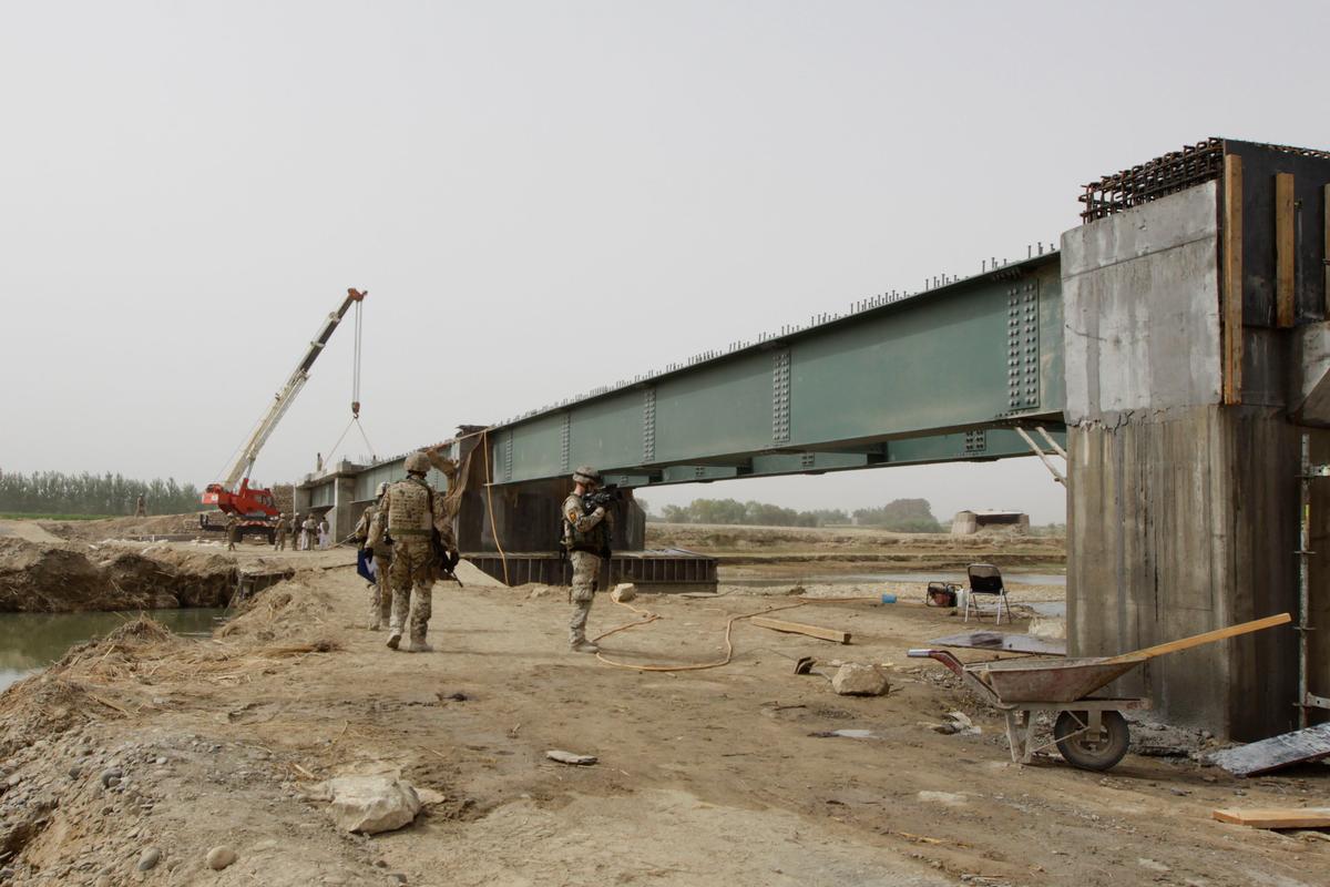
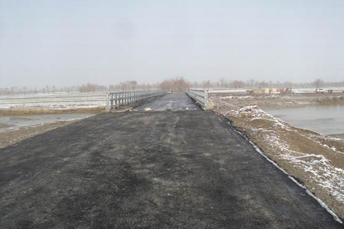
Due to the inadequate infrastructure in Kunduz Province, the infrastructure program for Afghanistan provided for the construction of a bridge over the Kunduz River. As part of the construction of a 6.00 m wide connecting road between the main routes „Pluto“ and „Little Pluto“, the approximately 80 m long bridge with two intermediate piers was built in the riverbed, approximately 7 km south of Kunduz airport near the towns of Omarkhel and Rhamat Bay.
Building design and construction
Northeastern Afghanistan is subject to increased earthquake risk. Magnitudes recorded to date have been in the range of 6 or more. A maximum ground acceleration of 6.72 m/s² is assumed for the Kunduz site and thus also for the structure [1], which corresponds to approximately 68% of the acceleration due to gravity. Due to the fact that the planning area experiences these strong earthquakes with great frequency, a robust and low-maintenance structure is required.
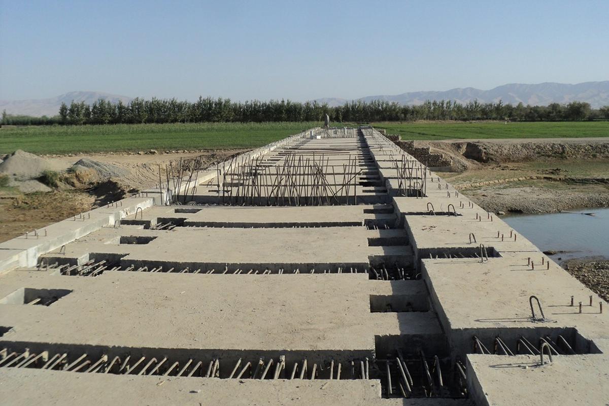
The bridge was therefore designed and built as a fully integral frame structure without bearings or joints. In terms of ist construction type, it thus represents a very durable structure with the lowest maintenance requirements, as well as an extremely advantageous solution in terms of earthquake effects.
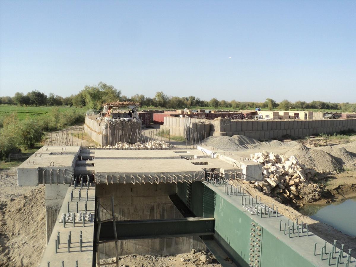
In view of the construction time, the transport of components from Europe (structural steel of the main girders), the limited availability of construction material and construction equipment on site, the efficiency of the local construction industry and the future maintenance expenses over the service life, a composite system with subsequent in-situ concrete grouting was selected for the superstructure cross-section.
Due to the slightly different terrain elevations on both banks, the structure was designed with a slope of 0.5% in the longitudinal direction, resulting in abutment stems of almost the same height that behave the same under load, especially in the event of an earthquake. Both abutments and the center columns are founded deeply on rolled section steel piles. The clean lines of the superstructure and the proportionally divided spans create a well-designed bridge structure.
Load approach/system
The following traffic load approach was carried out in coordination with the test engineer:
- Approach main and auxiliary lane (9 and 2.5 kN/m², respectively) according to DIN FB. Approach MLC 50 as overload (incl. Consideration of vibration coefficient) according to STANAG; braking loads according to STANAG
- Superposition with earthquake loads only with self-weight shares
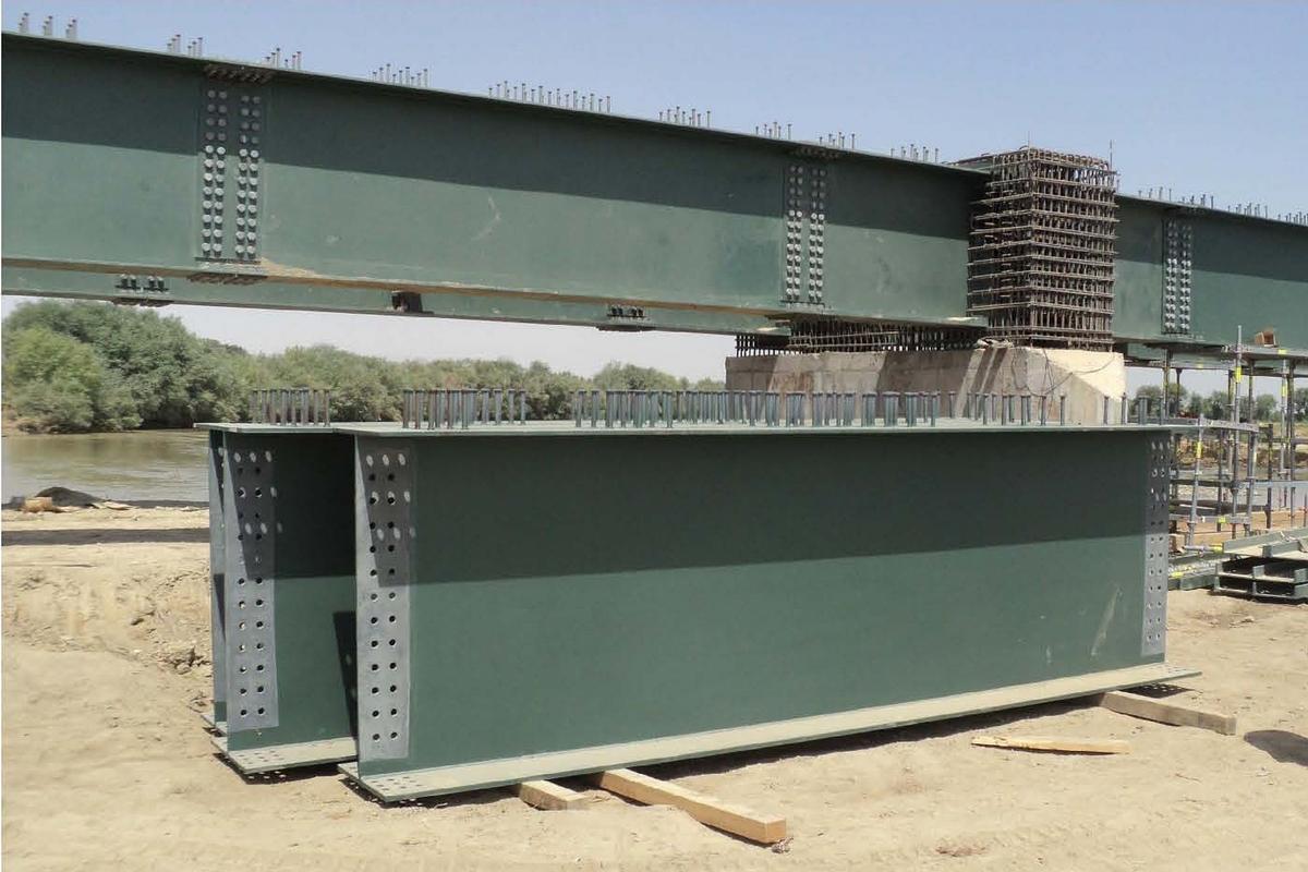
The superstructure is composed of a simple and proven steel girder grid of main girders and cross girders and a composite reinforced concrete slab above. To provide relief from constrained loads, the abutment walls are designed as approximately 4.40 m high stems that tie into solid pile cap slabs.
The structure has the following design features:
- Static system: 3-span composite frame
- Foundation: deep foundation with rolled section steel piles (total 90 pcs HE 300 B)
- Support widths: 25.00 m / 30.00 m / 25.00 m
- Light width: 79.00 m
- Superstructure: steel components in composite with precast reinforced concrete elements in cast-in-place concrete
- Construction height: 1.83 m
- Light height / freeboard: min. 1.00 m above assumed HHW
- Regulatory cross-section of structure:
- Parapet upstands: 2 x 0.45 m
- Lane width: 4.20 m according to local and military requirement
- Emergency walkway on one side: 0.80 m
- Total width between the railings: 5.00 m in standard cross-section
- Bridge area: 400 m²
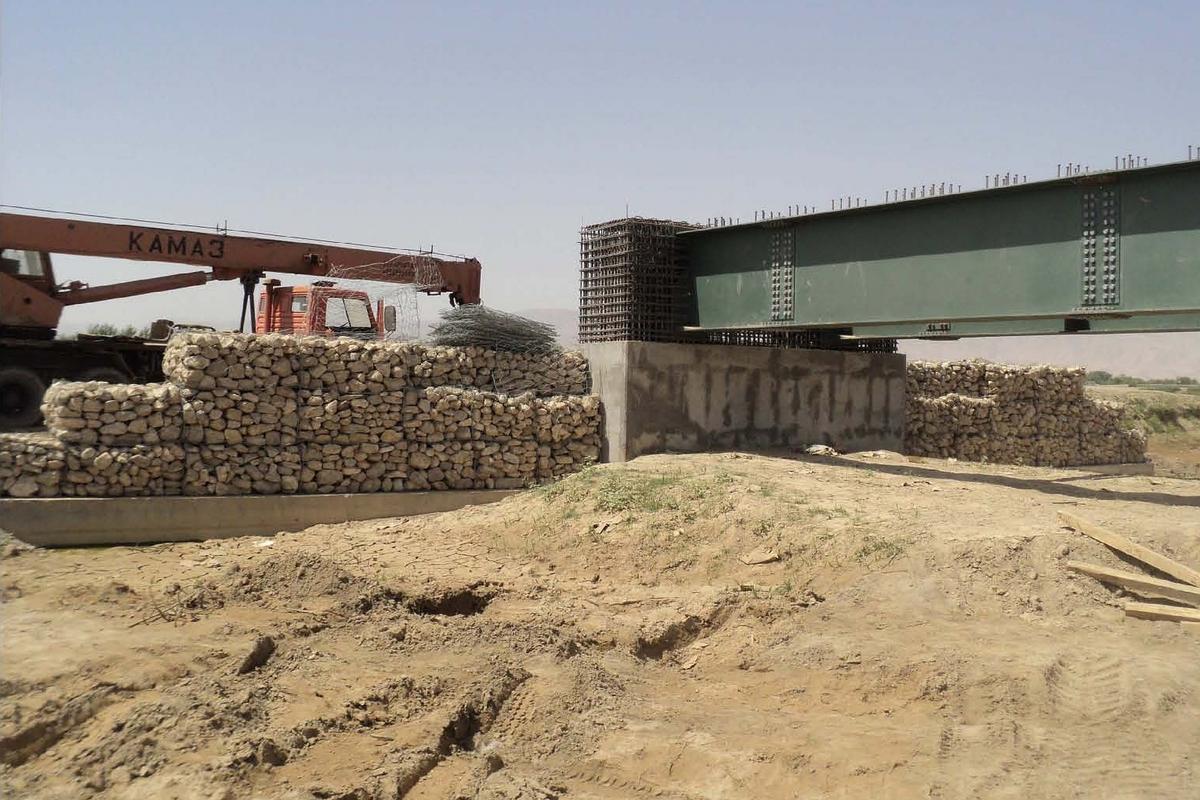
The wings to secure the embankment of the upcoming road embankments are made in extension of the abutment walls as heavyweight walls of gabions. To protect against scouring, the river piers in the foundation area circumferentially received a stone fill. The bank-side areas in front of the abutment walls were also provided with armourstones.
Construction implementation/local restrictions
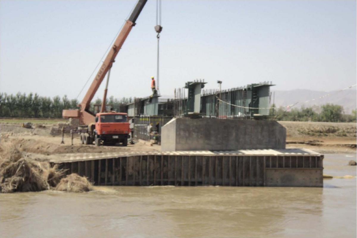
Precision steel construction does not exist in Afghanistan. It was therefore decided to have the steelwork fabricated in Germany and to assemble trial. The components, including the assembly scaffolding and the necessary (special) tools, were then packed in containers and transported to the construction site. Due to accessibility in the mountains, the maximum component dimensions were made up for 20-foot containers. For the structural design, limit states (link chain, cantilever) were taken into account so that certain leeway was possible on the part of the executing company in consultation with the structural engineer during assembly on site. The designed total weight of a weft is approx. 7.7 tons, the weft weight of a main girder is approx. 3.60 tons. Thus, well manageable erection / transport weights were achieved.
The pile drivers used for the deep foundation were equipment that is widely used locally for well construction. The blow counts as a function of pile driving depths and pile driving weights were evaluated to ensure the load transfer of the structure and to confirm the subsoil assumptions.
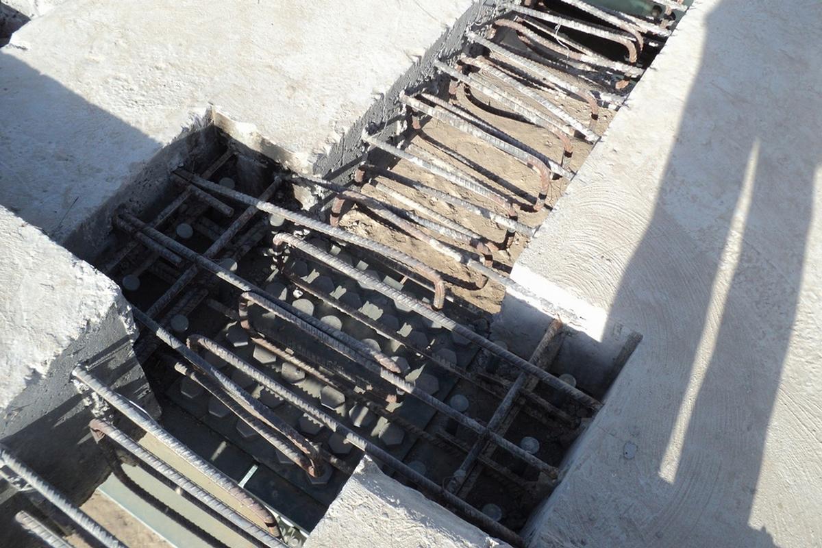
3D reinforcement drawings were prepared for the fabrication of the precast reinforced concrete elements with semi-skilled labor. This ensured the accuracy of fit of the grouting pockets with the shear bolt grid of the main beams.
Explanatory report by SSF Ingenieure AG for submission to the Ingenieurbaupreis 2013
Participants
-
SSF Ingenieure AG
- Andreas Röder (project manager)

-
SSF Ingenieure AG
- Andreas Röder (designer)
Relevant Web Sites

- About this
data sheet - Structure-ID
20064332 - Published on:
21/11/2012 - Last updated on:
15/04/2016


