
General Information
Project Type
| Function / usage: |
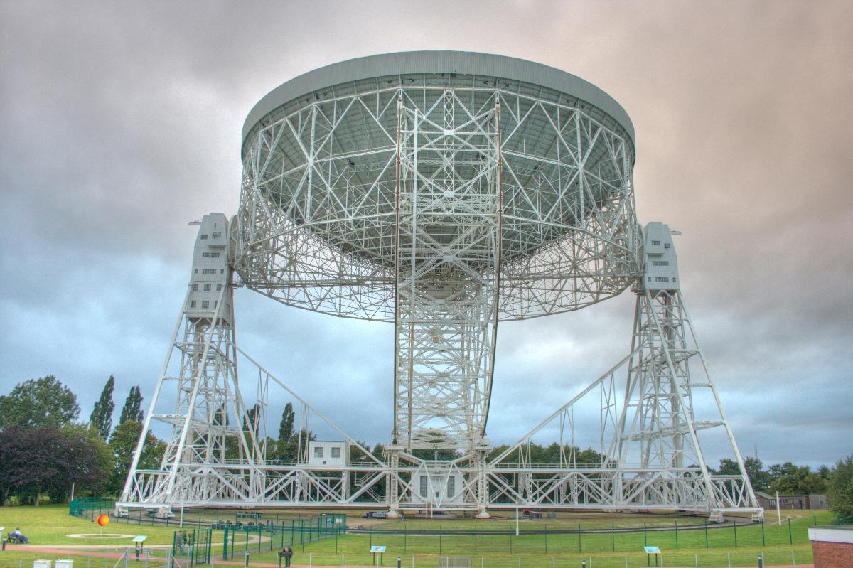
Radio telescope |
|---|
Location
| Location: |
Chester, Cheshire, North West England, England, United Kingdom |
|---|---|
| Coordinates: | 53° 14' 13.20" N 2° 18' 25.74" W |
Technical Information
Dimensions
| diameter | 76.2 m |
Excerpt from Wikipedia
The Lovell Telescope /ˈlʌvəl/ is a radio telescope at Jodrell Bank Observatory, near Goostrey, Cheshire in the north-west of England. When construction was finished in 1957, the telescope was the largest steerable dish radio telescope in the world at 76.2 m (250 ft) in diameter; it is now the third-largest, after the Green Bank telescope in West Virginia, United States, and the Effelsberg telescope in Germany. It was originally known as the "250 ft telescope" or the Radio Telescope at Jodrell Bank, before becoming the Mark I telescope around 1961 when future telescopes (the Mark II, III, and IV) were being discussed. It was renamed to the Lovell Telescope in 1987 after Sir Bernard Lovell, and became a Grade I listed building in 1988. The telescope forms part of the MERLIN and European VLBI Network arrays of radio telescopes.
Both Bernard Lovell and Charles Husband were knighted for their roles in creating the telescope. In September 2006, the telescope won the BBC's online competition to find the UK's greatest "Unsung Landmark". 2007 marked the 50th anniversary of the telescope.
If the air is clear enough, the Mark I telescope can be seen from high-rise buildings in Manchester such as the Beetham Tower, and from as far away as the Pennines, Winter Hill in Lancashire, Snowdonia, Beeston Castle in Cheshire, and the Peak District. It can also be seen from south-facing windows of the Terminal 1 restaurant area and departure lounges of Manchester Airport.
Construction
Conception and construction of the Mark I
Bernard Lovell built the Transit Telescope at Jodrell Bank in the late 1940s. This was a 218 ft (66 m)-diameter radio telescope that could only point directly upwards; the next logical step was to build a telescope that could look at all parts of the sky so that more sources could be observed, as well as for longer integration times. Although the Transit Telescope had been designed and constructed by the astronomers that used it, a fully steerable telescope would need to be professionally designed and constructed; the first challenge was to find an engineer willing to do the job. This turned out to be Charles Husband, whom Lovell first met on 8 September 1949.
Two circular 15" turret drive gear sets and associated pinions from 15-inch (38-cm) gun turrets were bought cheaply in 1950; these came from the World War I battleships HMS Revenge and Royal Sovereign, which were being broken up at the time. The bearings became the two main altitude rotator bearings of the telescope, with the appropriate parts of the telescope being designed around them. Husband presented the first drawings of the proposed giant, fully steerable radio telescope in 1950. After refinements, these plans were detailed in a "Blue Book", which was presented to the DSIR on 20 March 1951; the proposal was approved in March 1952.
Construction began on 3 September 1952. The foundations for the telescope were completed on 21 May 1953 after being sunk 90 ft (27 m) into the ground. it then took until Mid-March 1954 to get the double railway lines completed due to their required accuracy. The central pivot was delivered to the site on 11 May 1954, and the final bogie in mid-April 1955.
The telescope bowl was originally going to have a wire mesh surface to observe at wavelengths between 1 and 10 meters (3.2 and 32 feet), so frequencies between 30 and 300 MHz; this was changed to a steel surface so that the telescope could observe at the 21 cm (8 in) hydrogen line, which was discovered in 1951. Also, in February 1954 Lovell and the Air Ministry met to see if funding could be made available for improving the accuracy of the dish so that it could be used on centimetre wavelengths, for research at these wavelengths for the Ministry as well as "other purposes". Although the funding was not ultimately made available from the Air Ministry, the planning process had already progressed too far and so this improvement was made anyway.
The telescope was constructed so that the bowl could be completely inverted. Originally, it was intended to use a movable tower at the base of the telescope to change the receivers at the focus. However, the movable tower was never built, due jointly to funding constraints and the fact that much of the receiver equipment was placed at the base of the telescope rather than at the focus. Instead, receivers were mounted on 50-foot (15-m) long steel tubes, which were then inserted by a winch into the top of the aerial tower while the bowl was inverted. The cables from the receivers then ran down the inside of this tube, which could then be connected when the telescope was pointed at the zenith. Associated receiver equipment could then be placed either in the small, swinging laboratory directly underneath the surface; in rooms at the tops of the two towers; at the base girders, or in the control building.
The telescope moved for the first time on 3 February 1957: by an inch. It was first moved azimuthally under power on 12 June 1957; the bowl was tilted under power for the first time on 20 June 1957. By the end of July the dish surface was completed, and first light was on 2 August 1957; the telescope did a drift scan across the Milky Way at 160 MHz, with the bowl at the zenith. The telescope was first controlled from the control room on 9 October 1957, by a purpose-built analogue computer.
There were large cost overruns with the telescope's construction, mainly due to the steeply rising cost of steel at the time the telescope was constructed. The original grant for the telescope's construction came jointly from the Nuffield Foundation and the government; this amounted to £335,000. The government increased its share of the funding several times as the cost of the telescope rose; other money came from private donations. The final part of the debt from the construction of the telescope, £50,000, was paid off by Lord Nuffield and the Nuffield Foundation on 25 May 1960 (partly due to the telescope's early, very public role in space probe tracking; see below), and Jodrell Bank observatory was renamed to the Nuffield Radio Astronomy Laboratories. The final total cost for the telescope was £700,000.
Upgrade to Mark IA
Shortly after the telescope was originally completed, Lovell and Husband started contemplating the idea of upgrading the telescope so that it had a more accurate surface, and was controlled by a digital computer. Plans for this upgrade were created by Husband and Co., and were presented to Lovell in April 1964. Their plans became more urgent when fatigue cracks were discovered in the elevation drive system in September 1967. The telescope was only expected to have an operational lifespan of 10 years, and Husband had been warning about the decay of the telescope since 1963. The appearance of fatigue cracks was the first of these problems that threatened to stop the telescope working; had they not been put right the elevation system could have failed and perhaps jammed. The telescope was therefore repaired and upgraded to become the Mark IA; the £400,000 of funding to do this was announced on 8 July 1968 by the SRC. The upgrade was carried out in three phases, phase 1 lasting between September 1968 and February 1969, phase 2 between September and November 1969 and phase 3 between August 1970 and November 1971.
The first phase saw the addition of an inner railway track, which was designed to take a third of the weight of the telescope. The outer railway track, which had been decaying and sinking over the previous years, was relaid in the second phase. Four bogies and their steelwork were added on the inner track, and the existing bogies on the outer track were overhauled.
The third phase saw the biggest changes; a new, more accurate bowl surface was constructed in front of the old surface, meaning that the telescope could be used on wavelengths as small as 6 cm (5 GHz), and the central "bicycle wheel" support was added. A new computer control system was also installed (reusing the Ferranti Argus 104 computer from the Mark II); fatigue cracks in the cones connecting the bowl to the towers were repaired, and the central antenna was lengthened and strengthened. Tragically, in January 1972 the hoist carrying two engineers to the central antenna broke, gravely injuring two engineers and causing the death of one of them.
The Mark IA upgrade was formally completed on 16 July 1974, when the telescope was handed back to the University of Manchester. Due to increases in the cost of steel during the upgrade, the final amount for the upgrade was £664,793.07.
Later upgrades and repairs
The Gale of January 1976 on 2 January, brought winds of around 90 mph (140 km/h) which almost destroyed the telescope. The towers bowed, and one of the bearings connecting the dish to the towers slipped. After an expensive repair, diagonal bracing girders were added to the towers to prevent this happening again.
By the 1990s, the telescope surface was becoming badly corroded. In 2001–2003, the telescope was resurfaced, increasing its sensitivity at 5 GHz by a factor of five. A holographic profiling technique was used on the surface, meaning that the surface works optimally at wavelengths of 5 cm (compared to 18 cm on the old surface). A new drive system was installed, which provides a much higher pointing accuracy. The outer track was relaid, and the focal tower was strengthened so that it could support heavier receivers.
In 2007 the telescope needed a new drive wheel, as one of the 64 original wheels had cracked; in 2008 another new steel tyre was needed after a second wheel cracked. These are the only two wheel changes needed since the telescope started operation in 1957.
The presence (as at 2010) of two breeding pairs of wild peregrine falcons (nesting one in each of the telescope's two support towers) prevents the nuisance of pigeon infestation (by droppings fouling, and their body heat affecting sensitive instrument readings) that some other radio telescopes suffer from.
Statistics
- Mass of telescope: 3200 t
- Mass of bowl: 1500 t
- Diameter of bowl: 76.2 m = 250 ft
- Surface area of bowl: 5270 m² = 1.3 acres
- Collecting area of bowl: 4560 m² = 1.127 acres
- Height of elevation axis: 50.5 m = 165.68 ft
- Maximum height above ground: 89.0 m = 292 ft
- Radius of wheel girders: 38.5 m = 126.31 ft
- Outer diameter of railway track: 107.5 m = 352.690 ft
- Amount of paint for 3 coats of the bowl: 5300 L
- Azimuthal drive power: Two 50 horse power electric motors, one at the foot of each tower.
- Maximum drive rates 15 degrees per minute in azimuth, 10 degrees a minute in elevation.
Text imported from Wikipedia article "Lovell Telescope" and modified on July 23, 2019 according to the CC-BY-SA 4.0 International license.
Participants
Currently there is no information available about persons or companies having participated in this project.
Relevant Web Sites

- About this
data sheet - Structure-ID
20049578 - Published on:
10/12/2009 - Last updated on:
16/05/2015


