
General Information
Project Type
| Structure: |
Cable-stayed bridge with semi-fan system |
|---|---|
| Function / usage: |
Road bridge |
| Material: |
Prestressed concrete bridge Structurae Plus/Pro - Subscribe Now! |
| Secondary structure(s): |
Structurae Plus/Pro - Subscribe Now! |
Location
| Location: |
Sandnessjoen, Nordland, Norway |
|---|---|
| Crosses: |
|
| Coordinates: | 66° 2' 17.42" N 12° 43' 11.77" E |
Technical Information
Dimensions
| main span | 425 m | |
| deck | deck depth | 1.20 m |
| deck width | 12 m |
Materials
| cables |
steel
|
|---|---|
| deck |
prestressed concrete
|
| pylons |
reinforced concrete
|
General layout
Introduction
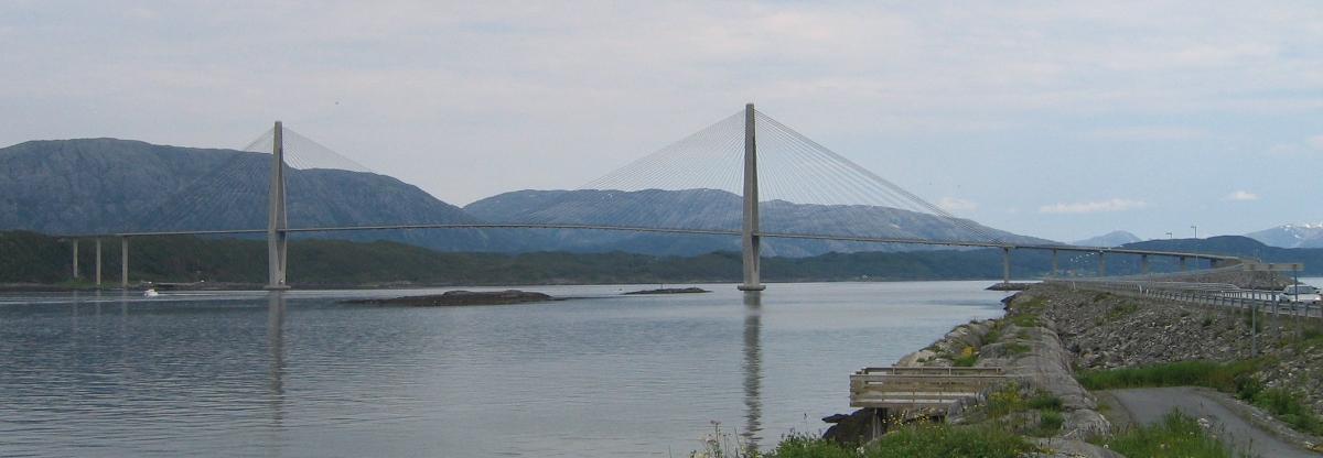
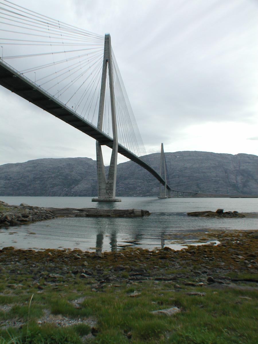
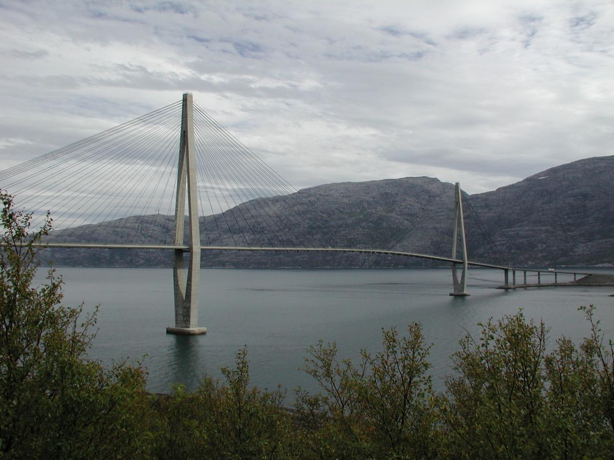
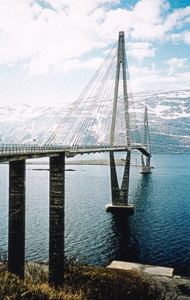
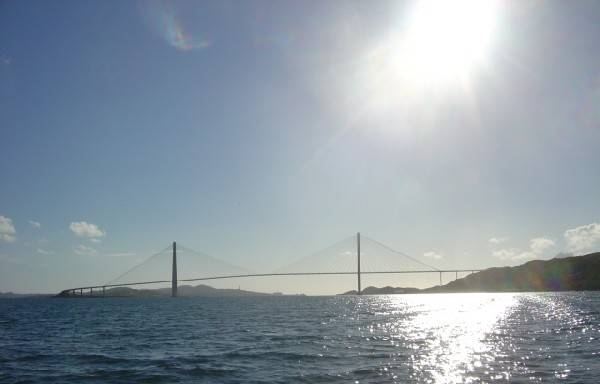
The Helgeland Bridge is a slender cable-stayed concrete bridge with a main span of 425 m. The aerodynamically shaped beam has a depth of 1.2 m and is 12 m wide. The towers are founded on rock in 30 m depth. The bridge is exposed to severe storms with gusts of up to 77 m/s wind speed. For the design of the governing loading ‘wind’, an analytical timehistory investigation in the ultimate limit state was performed, which took into account the aerodynamic damping as well as geometrical and material non-linearities. The bridge was built by free cantilevering from the towers outwards to both sides and was opened after a two-year construction period in July 1991. The beam was built with CIP concrete, which has the advantage that no heavy precast elements have to be transported and lifted. A disadvantage is that CIP construction requires about one to two weeks for each new beam section, whereas precast elements permit a construction progress of one to two elements per week. In order to reduce the construction period, long beam sections of 12 m, equal to the cable distance, were used. During casting the unsupported weight of the new section would have caused too high bending moments at the tip of the already completed beam. Therefore, the formwork carriage had to be tied back. If auxiliary tie-backs are used, their elongation for the next beam section is tedious and time-consuming. For the Helgeland Bridge the final cables were used to support the form traveler during casting. They were anchored in precast elements as part of the final beam which were bolted to the form traveler.
The Helgeland Bridge is located on the west coast of Norway on the Arctic Circle near the city of Sandnessjöen, crossing the Leirfjord between the island of Alster and the mainland. The geology in the surroundings of the bridge consists of granite which is partly eroded by ice age glaciers. The fjord is up to 130 m deep, nearly 400 m wide and has steep slopes at both sides. The initially proposed main span of 400 m had to be increased to 425 m in order to remove the tower foundations sufficiently from the fjord edges to safely avoid sliding of the granite slopes. The Gulf Stream prevents very low temperatures on site, but a real problemis the frequently occurring severe storms. In addition to the high gust speed of 77 m/s at beam level (+ 50 m) the turbulence intensity of 21 % is remarkable, caused by a mountain range close by (the „Seven Sisters“) in the main direction of wind. Ship traffic to the industrial harbor of Mosjöen in the hinterland requires a vertical navigational clearance of 45 m. The towers were designed for ship impact with an equivalent static load of 5 000 t. For live load the Norwegian codes require a 600 kN truck in addition to a uniformly distributed load of 3 kN/m². Regular high-strength concrete B 65 was used throughout. After an international tender the construction was awarded in April 1989 for about € 25 million to a Norwegian contractor.
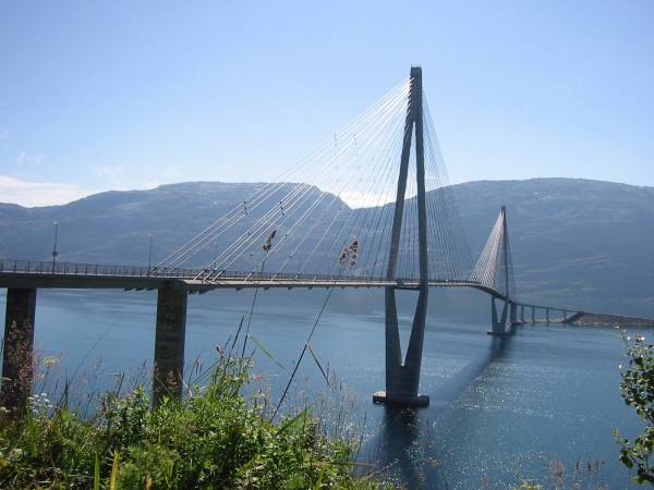
Bridge system
The topography required a main span of 425 m with appropriate side spans of 177.5 m. The low traffic level at this location near the Arctic Circle needed only two traffic lanes and one walkway. This led to a 12 m wide beam with a transverse slenderness of 1:36. The requirements for low wind resistance, aerodynamic stability and suitability for CIP construction led to an open cross-section with two solid edge girders and a beam depth of 1.2 m, giving a vertical slenderness of 1 : 354. The towers are A-shaped above the roadway in order to increase the torsional stiffness by coupling the two tower legs. Below the beam the tower legs merge on top of the single foundations. The beam is continuous between joints in the second approach span and is monolithic with all slender side span piers. At both towers the beam rests on 22 cm deep neoprene bearings which can deform horizontally. In this way the breaking forces and temperature changes of the beam are taken up by both towers simultaneously. Only small differences in tower action forces are caused by the different lengths of the approaches and tower heights. Both towers are therefore sized identically.
Bridge beam
For the very slender bridge beam partial post-tensioning in both directions was selected in order to ensure sufficient ductility. In the edge girders, four Type 1 continuity tendons were arranged over the full bridge length, and these were coupled at each construction joint. At the end of beam construction additional continuity tendons, Types 2 and 3, were threaded into empty ducts and grouted in the center of the bridge and in the end regions. Cross girders are located at the cable anchorage points at a distance of 12.9 m which contain the only transverse post-tensioning. The 40 cm thick roadway slab spans 12.4 m longitudinally and 7.5 m transversely between the main and cross girders. The sizing of the beam was governed by the following loadings: a) permanent loads plus live loads b) turbulentwind c) loads during construction. For loading a) the non-linear characteristics of the bridge (P-Δ effect) and the material (elastic-plastic) were taken into account. The increase of live load moments reached up to 50 % against the linearly calculated moments because of the extreme slenderness of the beam (1:354). The governing loadings during construction for positive beam moments were stressing of the stay cables to final lengths and, for negative moments, the situation after forwarding the formwork carriage, before installation of the corresponding stays. The sizing was done in the ultimate limit state. Under service conditions the crack width was limited to 0.2 mm generally and to 0.1 mm at the tendons. This is true under 60 % of live load as well as for wind alone, or during all construction stages. At the same time, the steel stresses in the cracked tensile zone are limited to 190 N/mm². The chosen posttensioning is sufficient to avoid longitudinal tensile stresses under permanent loads plus frequently occurring live loads. The four tendons with nine ½” strands in each edge girder (Type 1) were mainly required during construction. This partial prestress permitted the optimization of the amount of reinforcement for the final stage and during construction. The stay cables rest on corbels underneath the edge beams and run through cast-in steel pipes to the tower heads. This type of stay-cable anchorage has proved to be very expedient since the opening of the Pasco-Kennewick Bridge, USA, in 1978.
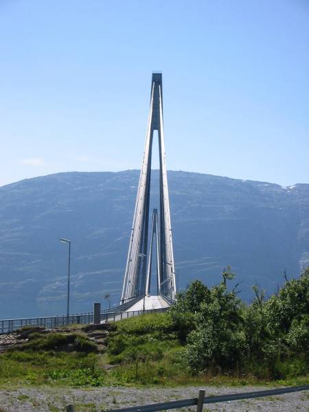
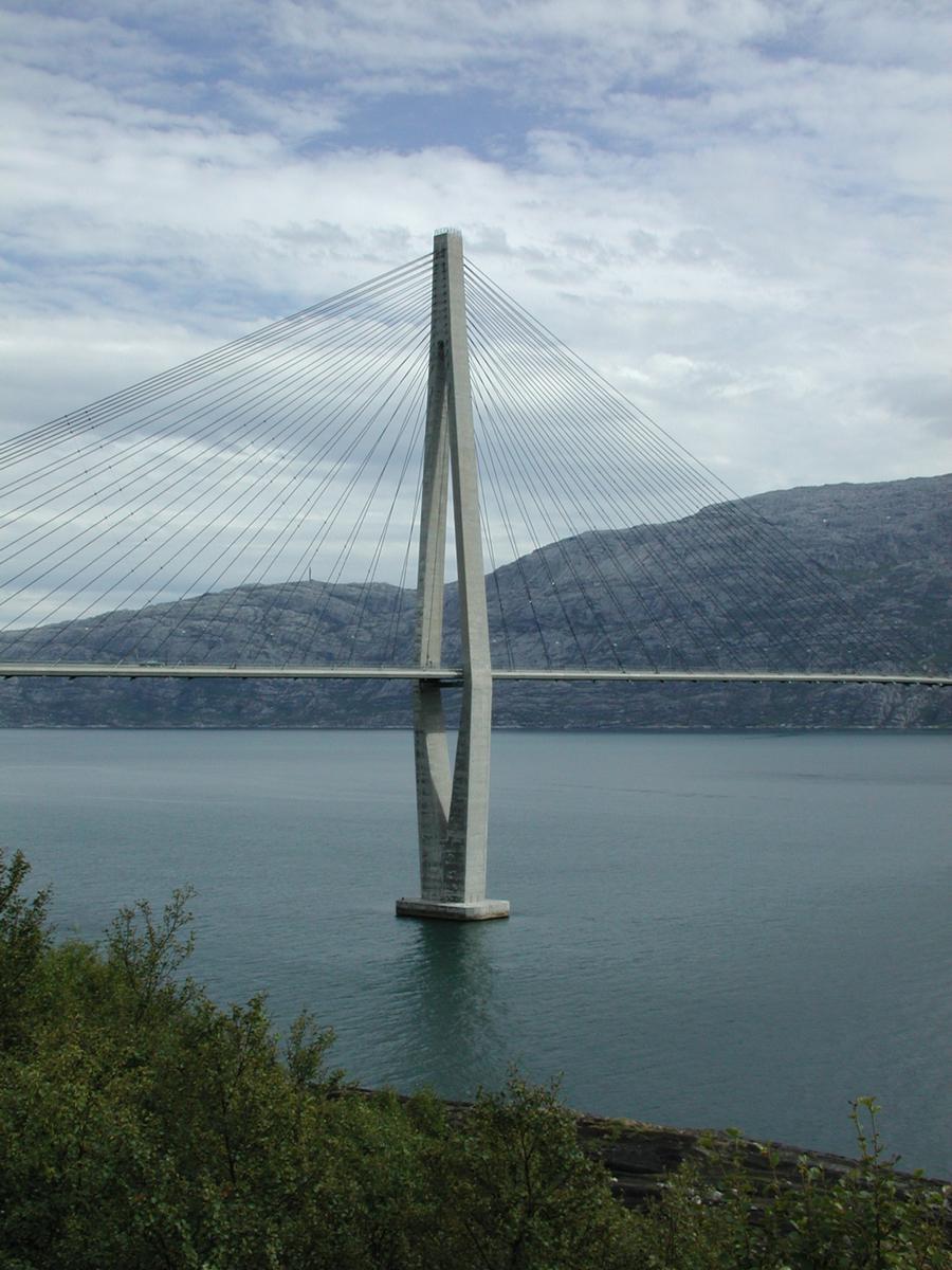
Towers
The diamond shape was chosen because of economy, aesthetics and improved torsional resistance of the beam. The towers are stiff transversely, and in the longitudinal direction the tower head is restrained by the backstay cables. Because independent movements of both A-tower legs are prevented, the influence of the backstay cables during rotational oscillations of the beam is omitted and the torsional frequency is thus importantly increased. During construction auxiliary piers were required in both side spans in order to reduce the weather-vaning horizontal moments on the tower by the beam, created by differential wind on the two cantilevers. These auxiliary piers were stressed with tendons onto the rock. The connection with the beam was vertically sliding in order to avoid moment peaks in the beam. The tower legs are solid underneath the beam to provide sufficient downloads for the solid foundations in up to 30 m water depth. Above the beam they have box girder cross-sections with 40 cm wall thickness. The stay cables are anchored inside the concrete tower heads. The horizontal cable components are carried by loop tendons, which also permit exchange of any single stay cable. A test with a full-size model showed that by using thick, smooth and lubricated pipes for tendons the usual friction coefficients were not exceeded even in the regions of high curvature with a radius of 0.8 m. In this way, expensive additional transverse post-tensioning is avoided. Vertical cracks did not occur. The loop tendons and the transverse reinforcement were sized in the ultimate limit state by a strut-and-tie model, and, in addition, for bending and normal force during service.
Stay cables
The stay cables were sized in accordance with the PTI Guidelines for galvanized wires, ø 7 mm, steel 1450/1650. The 4 × 32 stay cables with lengths between 64 m and 225 m required between 67 and 231 wires. The governing loading was permanent loads plus live load for a permissible stress of 0.45 ultimate under service conditions. The wires are covered by PE pipes and end in anchor heads with a cold casting from steel balls and epoxy resin, called HiAm. Cement grouting of the PE pipes on site was not possible because the temperatures would have been too low. Therefore, a petroleum wax was injected into the PE pipes during shop fabrication.
Aerodynamic stability
The exposed location of the bridge with regard to wind, and its great slenderness, required an especially careful investigation of the wind response,both during construction and in the final stage, which was done to a large extent analytically. An in-house developed time-history method was used, which simulated the wind in such way that not only the spectrum but also all the other characteristics were fulfilled. In this connection the tilting of the beam under transverse bending in the center of the bridge is important, where the restoring due to the cables is small because of their flat angle.
Wind simulation
The wind speed at ultimate limit state is generated from those in service limit state by a √γω increase. The 10-min mean at beam level for a 50-year probability in the ultimate limit state thus resulted in a wind speed v(ultimate) = √1.6 • 50 = 63.25. The tender documents prescribed the turbulence spectrum in accordance with ESDU 1974, gives the turbulence components from the ESDU spectrum simulated by 1/12-octave-components. The exactness with which the turbulences were generated by 128 harmonic components was considered sufficient for the wind simulation.
Sizing
The non-linear effects were calculated for in a sizing program, taking into account the geometrical stiffness of the cable system with the chosen forces as well as buckling and tilting effects. The force–deformation behavior at the nodes was corrected continuously in an iteration process. In order to account for the revised reinforcement in each step a parallel program for skew bending was used for parametric studies. The high moments in the tower region during construction and the corresponding high amount of reinforcement there resulted in plastic rearrangement of moments which reduced the moments in the center of the span. This effect was further enhanced by the resulting reduction of the span reinforcement.
Windtunnel tests
The wind tunnel tests performed on an elastically supported, dynamic section models showed that aerodynamic instabilities are not probable. The same was true for vortex excitation. The tests with a full model in a boundary layer wind tunnel showed as usual the largest amplitudes in turbulent wind. The Helgeland Bridge is a very daring design with a vertical beam slenderness of 1:354 and a horizontal slenderness of 1:36 in an area with very strong turbulent storms. The detailed aerodynamic investigation proved a sufficient safety not only for the final stage but also during construction. The bridge was indeed stable during construction, although the anticipated severe storms for a 50-year probability did indeed occur.
Construction
Climate
Due the location of the bridge on the west coast of Norway near the Arctic Circle, difficult weather conditions had to be taken into account for the construction planning. The problem was not low temperatures, as these were prevented by the influence of the Gulf Stream, but severe storms which regularly occur during winter months. The free cantilevering for 210 m from each tower with a beam depth of only 1.2 m was a very daring undertaking. The contractor planned the job site installation in such a way that continuous work, partly around the clock, was possible even during strong winds. Large pontoons (40 m × 100 m) were anchored at each tower as working platforms. The batching plant with a capacity of 60 m³/h, together with the aggregates and the cement silo, were located here. So not only the bridge but also the working pontoon with the equipment were endangered by the storms.
Towers
The tower foundations were built 30 m under water with tremie concrete for which a special mix was developed to prevent segregation during batching. Foundation construction started with placing a base layer of concrete by divers on the prepared rock surface. The precast elements for the underwater parts of the tower were cast on shore and floated to the site. The precast elements were lowered onto the prepared foundation with a floating crane, stressed together under water and filled with CIP concrete. In this way, the required DW was created to prevent tension underneath the foundation and to create sufficient resistance against ship collision. Above beam level the tower legs consist of concrete boxes with a wall thickness of 40 cm. They were concreted with sliding forms. The steel forms were enclosed and provided with an insulating skirt including heating elements to protect the fresh concrete against low temperatures. The progress of the sliding forms came to 1.5 m/day for the lower solid tower legs and reached up to 3 m/day above deck. In the cable anchorage region the tower were built in 3 m sections. Even in this difficult area with many built-in items, including the cable anchorages, sliding forms continued to be used, because the contractor considered it too risky to use a 3 m free cantilevering jumping form in strong winds. The steel pipes with their support plates were welded in shop to steel frames which were lifted in 3 m sections to the tower head and bolted to the previously installed frame. In this way the cable anchorages were safely kept in place during sliding.
Beam
The beam was designed from the beginning in such a way that it could be built CIP by free cantilevering from the towers outwards to both sides in sections of 12.90 m, equal to the cable distances. It was also planned during the design phase to support the travelers by permanent stay cables. Finally a stiff traveler was used which was stressed onto the already completed beam. Its lateral trusses carried an excess cable force before casting, back to the completed beam. Each traveler weighed about 115 t. As the tower legs, the traveler had to be provided with an enclosure for protection of the fresh concrete against cold winds. The additional wind load on this area would have created too high transverse bending moments for the beam. It was therefore decided to use light plastic sheets for protection, which would have been blown away by a severe storm. This illustrates that the beam was used to its limits during construction. In order to fix the position and the direction of each cable anchorage precisely against the beam, the steel pipes with their base plates were cast into a short precast element. The aprecast anchorage element have blockouts for the transverse tendons. (In later bridges the precast elements were avoided and the cable anchorage part of the beam was cast ahead in the form traveler. In this way the transportation was not required, but a longer construction period resulted.) Each of these precast elements was bolted in its final position to the form traveler so that the final stay cables could be installed and preliminarily stressed to a low level to support the form traveler during casting. The horizontal compression component of the inclined stay cable was carried by a precast strut from the precast anchorage element to the bulkhead of the already completed beam. Each precast element weighed 15 t and 24 t of reinforcement were placed before installation of the stay cables. The approach bridges were built with a spanwise self-launching form, together with the towers. The bottom form of the traveler alone was supported directly from the towers for casting the beam starter section. After completion the travelers were assembled on the starter sections and free cantilever construction could proceed. It was necessary to build auxiliary piers at the quarter-points of the side span. These were to take the horizontal forces from unbalanced transverse wind on the beam. The towers would not have been able to carry the weather-vaning moment by itself. The connection to the beam was vertically sliding in order to prevent the high moments created by a rigid support in between the elastic cable supports. At the end of construction the auxiliary piers were blasted and served as a new habitat for the fish in the fjord. The free cantilevering took place only slightly staggered for both towers. Shortly before closure of the center joint with the longest cantilevers of about 210 m each, a severe storm took place again. The bridge stood firm and the measured beam deflections were as calculated. Finally one formwork traveler was moved across the center joint and the closure pour took place. The geometry and action forces were adjusted in such a way that, after shrinkage and creep, the desired gradient and run of moments appeared.
Stay cables
Cable installation
The cables were transported on reels by ship from their place of fabrication in Zurich, Switzerland, to the site and lifted up to the beam. The tower crane then lifted each cable anchor to the tower head where it was threaded into the steel pipe and anchored inside the tower head with shims. The lower cable head was pulled with grip hoists near the steel anchor pipe in the beam. Then a tensioning rod was screwed into the inside thread of the anchor head. It can be seen clearly that the beam at this stage was not yet concreted, but that the reinforcement was already in place. The tensioning rod protrudes far enough beyond the underside of the beam that a center hole jack could be placed onto the jack chair in order to pull the cable into its final position. At this stage the stay cable had a greater length than in the final stage because the concrete weight was still missing.
Cable oscillations
During free cantilevering some of the foremost cables oscillated during strong winds with amplitudes the size of several cable diameters. This is a phenomenon well-known from the construction of other bridges. The reasons are the large sag of the stay cables due top missing beam loads and the flexibility of the beam tips during free cantilevering which both encourage oscillations in the wind. These may lead to large cable amplitudes caused by so-called anchorage excitation. As a counter-measure the stay cables can be tied down to the beam at a height of about 3 m with simple hemp ropes, which provide a degree of damping by internal friction. This measure proved effective, as it had for other bridges. During the first winter after completion, cable oscillations took place under very strong winds, probably also caused by anchorage excitations at the beam or at the towers. These oscillations became so strong that even the small movements between PE pipes and the neoprene washers at the tips of the steel pipes, partly destroyed the neoprene. This phenomenon could be repeated in tests at the EMPA in Zurich. These tests also showed that a stainless steel sheet between PE pipe and neoprene ring prevents damage of the neoprene. The PE pipes were therefore locally thickened and protected by steel sheets. Analysis of videos of the oscillating stay cables showed that an amplitude of up to 0.67 m was reached at a wind speed of 30.2 m/s. A theoretical investigation assuming anchorage excitations led to the same results. In order to suppress these cable oscillations, hydraulic and friction dampers were investigated. For easier maintenance, however, 4 × 3 tie-down strands of stainless steel ø 15 mm per cable plane were installed with a force of 220 kN in order to prevent slackening. Unfortunately, these tie-downs disturb the appearance of the bridge and make it difficult to inspect the cables with carriages running on them.
Instrumentation
During the winters between 1992 and 1994 the bridge was instrumented. The calculated values were a little bit too low for the horizontal deformations and a little bit too high for vertical deformations. The horizontal and vertical beam accelerations varied only slightly.
Completed bridge
The bridge was opened on midsummer night, 21 June 1991. At 425 m the Helgeland Bridge has the third longest concrete main- span after the Skarnsundet Bridge, Norway, at 530 m, and the Barrios de Luna Bridge in Spain at 440 m. In spite of its record slenderness of 1:354 and the occurrence of powerful storms during construction the Helgeland Bridge was completed within just two years.
Excerpt from: Svensson, Holger; Cable-Stayed Bridges, Wilhelm Ernst & Sohn Verlag für Architektur und technische Wissenschaften GmbH, Berlin (Germany), ISBN 343302992X; pp. 352-368. References to figures and literature were omitted.
Participants
- Holger S. Svensson (designer)

Relevant Web Sites
There currently are no relevant websites listed.
Relevant Publications
- (2002): 30 Bridges. Laurence King, pp. 190.
- : 30 Brücken. Callwey Verlag, Munich (Germany), pp. 192.
- (1992): Analytical Aerodynamic Investigation of Cable‐Stayed Helgeland Bridge. In: Journal of Structural Engineering (ASCE), v. 118, n. 1 (January 1992), pp. 147-168.
- (1994): Analytische aerodynamische Untersuchung der Schrägkabelbrücke Helgeland. In: Beton- und Stahlbetonbau, v. 89, n. 6 (June 1994), pp. 149-153.
- (2002): Bridges - Ponts - Brücken. Atrium, Mexico City (Mexico), pp. 234-239.
- About this
data sheet - Structure-ID
20000602 - Published on:
21/01/2000 - Last updated on:
25/08/2023


