
Digital hydraulics helps to position railway bridge
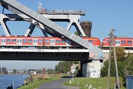
Local conditions sometimes make it impossible to build a bridge on site. In those cases the bridge must be assembled on an adjacent site and then be moved into its final position. This also happened in the Brussels district of Schaerbeek, where a steel railway bridge with a length of 140 m and a weight of over 1600 t had to be slid across a number of existing tracks. Enerpac was asked to monitor hydraulically the movement and forces that occurred during the sliding operation with its digital "Synchronous Lifting System”, and to make corrections if necessary.
Media
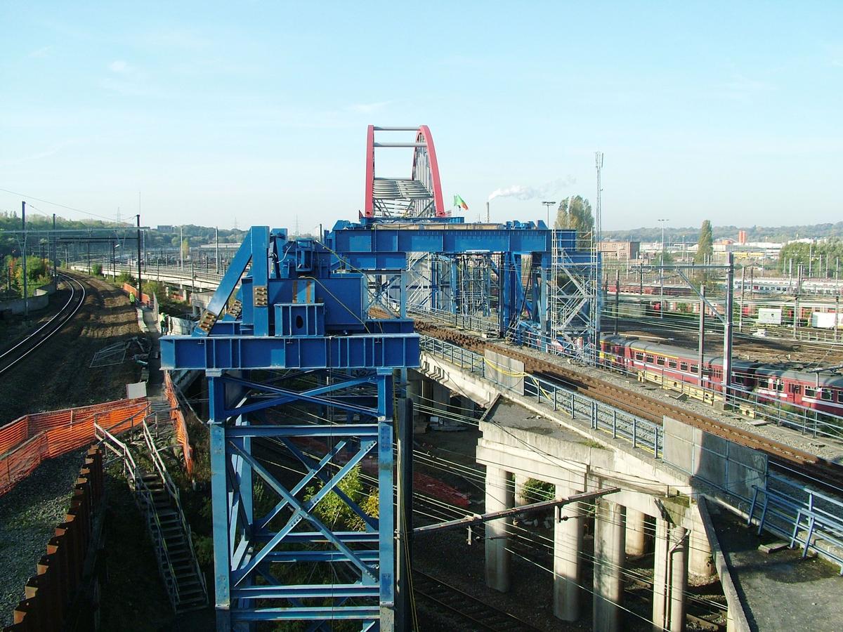
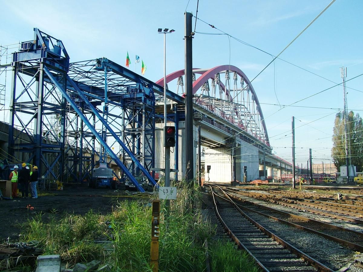
This new railway bridge in Brussels was built for Belgian Railways by Victor Buyck Steel Construction, a large Belgian steel construction company with international operations. The bridge was supplied in parts and assembled on one side of the newly built railway viaduct. The bridge was ready to be moved to its final position by the end of October 2008. Because of the intensive use of the railway tracks the bridge had to span across and the fact that railway traffic had to be stopped during the sliding operation, the contractor was given only 48 hours to move the bridge to its final position.
Complex combined force actions
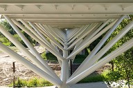
A steel structure may be referred to as rigid and inflexible, but this is totally untrue, especially in case of a steel railway bridge with a length of 140 m and a weight exceeding 1600 t. Enormous forces are developed during the movement. Under the influence of these forces the steel construction and in particular the superstructure are subjected to high, varying stresses and will certainly bend.
In order to ensure that the combined force actions would develop evenly during the movement of the railway bridge and to prevent the stresses from becoming excessive, the pulling and pushing forces occurring had to be measured, and reduced if required. In addition, the vertical position of the bridge had to be monitored, of course. Manual monitoring and correction of the movement is too inaccurate in such cases. Too much variation at the different points of support results in unacceptable stresses that may affect the construction. Besides, manual monitoring and correction is time-consuming and the contractor did not have much time. Therefore, Enerpac was asked to guide the movement of the railway bridge with its "Synchronous Lifting System” that has proved itself all over the world in the meantime.
Platform wagons and strand jacks (cable-lift cylinders)
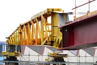
For the first phase of the movement a series of hydraulically controlled, multi-axle platform wagons, so-called supertransporters, were used on both sides beneath the bridge as the rearmost support points. For the second phase – the wagons could only reach a certain point – use was made of a hydraulic pulling system with "strand jacks”, cable strands that pull the bridge metre by metre over the remaining distance. Apart from that, a hydraulic retracting and braking system was provided because the railway bridge had to be launched on a downward slope with a level difference of 2 m.
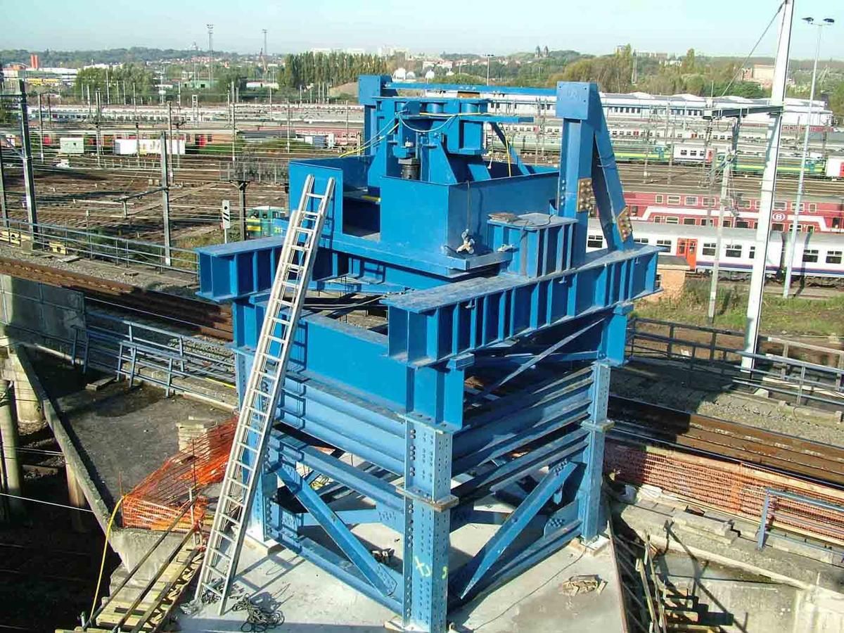
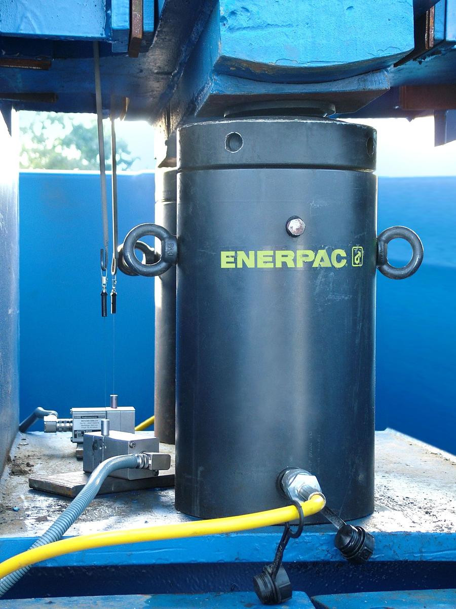
Eight temporary steel pillars were built to support the viaduct parts during the movement. Each pillar had been provided with a "draw beam”, a pivoting steel cross with heavy springs to compensate for the forces in the lower beam of the bridge plus the angular displacement and bending. Two hydraulic cylinders were mounted beneath each draw beam. The primary function of these cylinders was to keep the construction at the correct height. In order to reduce the resistance as much as possible during the movement, Teflon gliding plates were applied between the draw beam and the lower beam. In additional, a launching nose (beak) was provided at the front end of the bridge for a better distribution of the forces and for limiting the bending and tension during the movement.
Forces under control
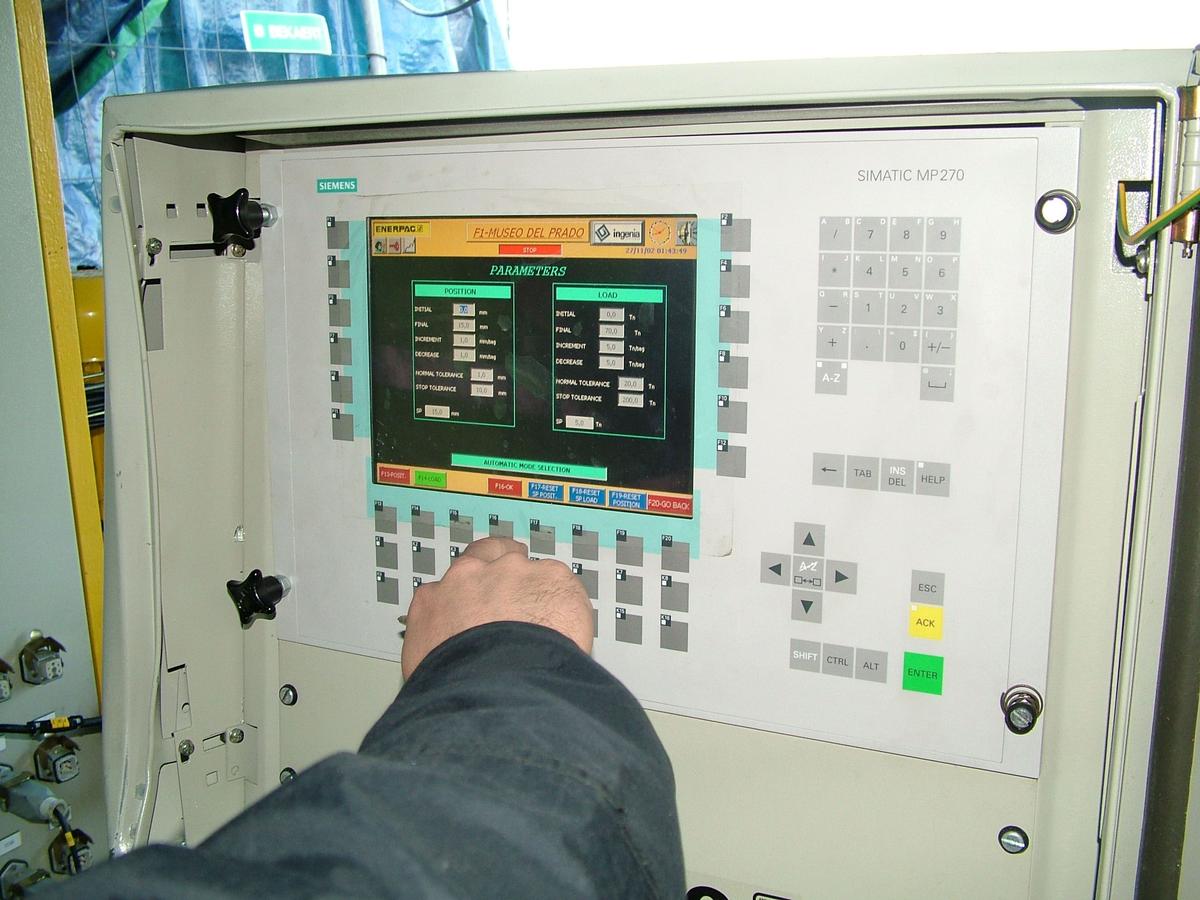
Victor Buyck Steel Construction accurately calculated beforehand the forces and tension actions that could occur at each support point during the movement. In order to be able to control this complex combination of forces and to make corrections if necessary, Enerpac installed a monitoring system specially devised for this. The system consisted of a total of 32 measuring points (28 of which were used) on an equal number of hydraulic cylinders, a central pump unit with a pressure of 700 bar, PLC and a computer system showing all movements and forces. Thanks to Enerpac, the work proceeded much faster than expected.
Both the hydraulics and the electronics of the system were designed and developed by a team of experts in the Enerpac Centre of Excellence in Spain. Enerpac itself hired out the equipment to the client, in accordance with the policy pursued with respect to such large projects. The installation and implementation were taken care of by the so-called Heavy Lift Team, experienced Enerpac experts from the UK. The total project period – installation phase, test phase, implementation and completion – lasted two weeks.
Synchronous Lifting System: digital hydraulics
Enerpac’s integrated and automatic "Synchronous Lifting System” is a combination of hydraulics and digital monitoring plus control. Irrespective of whether a bridge or a large building is concerned, this system offers an extremely effective method for both vertical and horizontal movement and positioning.
The total system is built in such a way that the different measuring points and cylinders are stable and do not influence each other, and it checks the measuring path and force. To do this, the control receives electronic signals from the movement sensors and the pressure in the cylinders is also transmitted electronically through sensors. The computer continuously calculates the force on each cylinder using pressure sensors. The system checks the position and movements of the individual cylinders and controls pump and valves if necessary to keep the forces at the correct value. In this way each point of the object is moved automatically and fully synchronically, and positioned with millimetre accuracy. When the force is outside a set value, the pressure is "adjusted”. The speed of the computer is exploited here to send short pulses quickly to the hydraulic valves. The result of this is that the individual cylinder movements can be many times smaller than with manual operation. The moment a cylinder movement is outside the tolerance, a warning signal is sent and the entire movement is stopped manually or automatically.
References

Structure Types

- About this
data sheet - Product-ID
6276 - Published on:
16/05/2013 - Last updated on:
30/01/2016