
General Information
| Other name(s): | Strelasundbrücke; Rügenbrücke |
|---|---|
| Beginning of works: | 31 August 2004 |
| Completion: | 20 October 2007 |
| Duration of works: | 39 months |
| Status: | in use |
Project Type
| Structure: |
Cable-stayed bridge with harp system Three-span cable-stayed bridge |
|---|---|
| Secondary structure(s): |
Structurae Plus/Pro - Subscribe Now! |
| Function / usage: |
Road bridge |
| Material: |
Steel bridge Structurae Plus/Pro - Subscribe Now! Structurae Plus/Pro - Subscribe Now! |
Location
| Location: |
Stralsund, Vorpommern-Rügen, Mecklenburg-Western Pomerania, Germany |
|---|---|
| Next to: |
Ziegelgrabenbrücke
|
| Coordinates: | 54° 18' 28.79" N 13° 6' 39.76" E |
Technical Information
Dimensions
| vertical navigation clearance | 42 m | |
| bridge 1.1 | total length | 327.5 m |
| span lengths | 29 m - 30.5 m - 7 x 33.5 m - 32.5 m | |
| number of spans | 10 | |
| bridge surface | 4 913 m² | |
| bridge 1.2 | total length | 317.0 m |
| span lengths | 48 m - 49 m - 72 m - 2 x 49 m - 48 m | |
| number of spans | 6 | |
| bridge surface | 4 755 m² | |
| bridge 2 | total length | 583.3 m |
| span lengths | 54 m - 72 m - 126 m - 198 m - 72 m - 59.2 m | |
| number of spans | 6 | |
| bridge surface | 8 720 m² | |
| bridge 3 | total length | 532.3 m |
| span lengths | 52.32 m - 8 x 53.33 m - 52.22 m | |
| number of spans | 10 | |
| bridge surface | 7 985 m² | |
| bridge 4 | total length | 532.2 m |
| span lengths | 52.22 m - 8 x 53.22 m - 52.22 m | |
| number of spans | 10 | |
| bridge surface | 7 983 m² | |
| bridge 5 | total length | 539.0 m |
| span lengths | 53 m - 8 x 54 m - 53 m | |
| number of spans | 10 | |
| bridge surface | 8 085 m² | |
| deck | deck width | 15.0 m |
| pylon | width | 20.586 m |
| height | 126 m |
Quantities
| substructure | concrete volume | 25 200 m³ |
| reinforcing steel | 2 400 t | |
| superstructure | structural steel | 7 286 t |
| concrete volume | 22 150 m³ | |
| prestressing steel | 676 t | |
| reinforcing steel | 3 655 t |
Cost
| cost of construction | Euro 100 000 000 |
Materials
| pylon |
steel
|
|---|---|
| piers |
reinforced concrete
|
| deck of main bridge |
steel
|
| deck of approach viaducts |
prestressed concrete
|
Strelasund Crossing - A Steel Cable-Stayed Bridge
Design Considerations
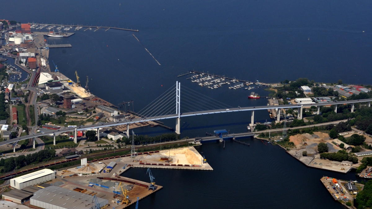
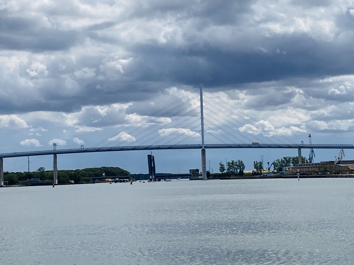
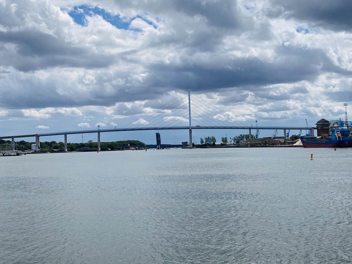
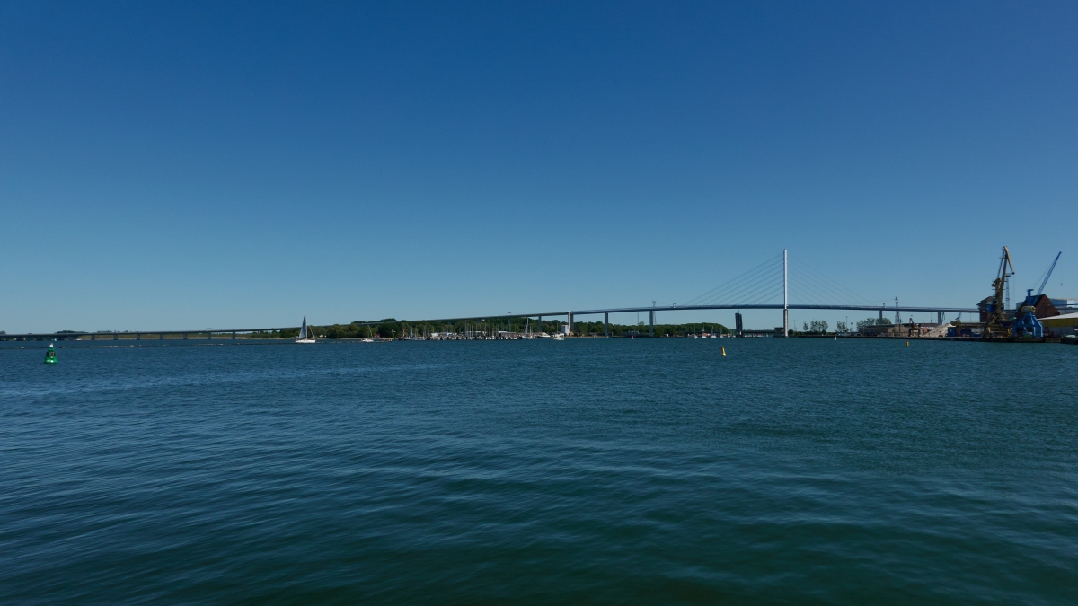
The second bridge across the Strelasund, in Germany, connects the island of Rügen with the mainland.
The complete Strelasund Crossing with a total length of 2830 m runs across the east part of the city of Stralsund, the Ziegelgraben waterway, the island of Dänholm and the Strelasund itself. It consists of six individual bridges, four prestressed concrete bridges, one steel composite bridge and the cable-stayed bridge with a steel box girder supported by one single, 128 m high steel tower.
Remarkable from an engineering point of view are – in addition to the variety of different structures within the total bridge – the unusual number of structural innovations, including the first use of parallel-strand cables for a major German bridge.
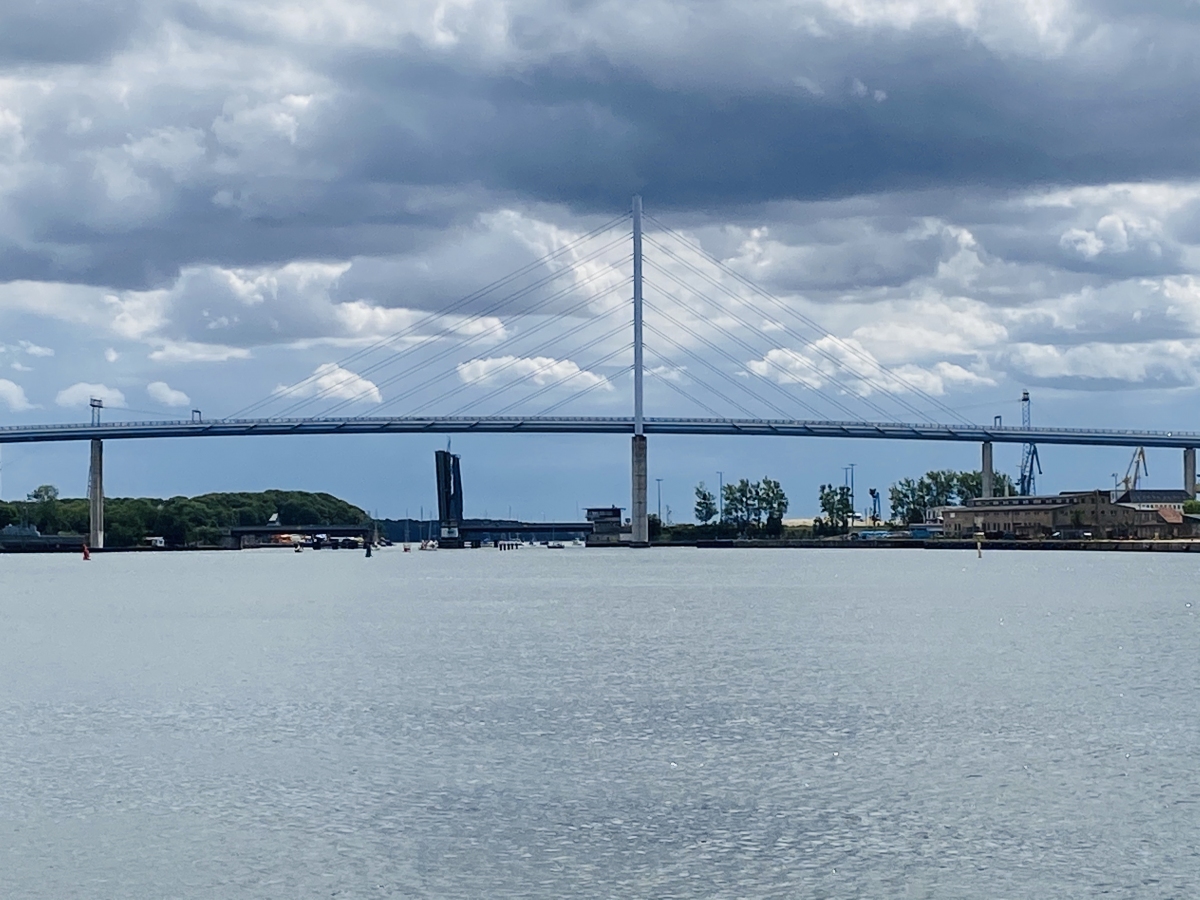
The second Strelasund Crossing runs parallel to the Rügen Causeway, some 100 m away from the old quarter of the city of Stralsund which is part of a UNESCO World Heritage Site. The required navigational clearance of 42 m results in a gradient 48 m above ground. The bridge dominates the view of the city and the designers, therefore, tried to develop an optically unobtrusive and elegant bridge.
Special care was provided for the ‘Guide Structure’, the roughly 200 m wide crossing of the Ziegelgraben waterway which was the starting point for the development of the design in several steps.
Bridge Alternates
For a span of 200 m, alternative designs for arch bridges, girder bridges and cable-stayed bridges were compared for aesthetic, technical and economic criteria.
Most important for judging the urban impact at the given location were visualizations. Initially the arch bridge was favored, but later it became apparent that the large dimensions in reality dominated the medieval silhouette of Stralsund too much. Furthermore, the arch required the biggest span for keeping the navigational clearance completely free, which led to very substantial cross-sections with the corresponding higher costs.
The steel-composite haunched girder bridge had economic advantages but had to be discarded from an aesthetic viewpoint because the unbalanced proportions and the optical barrier effect of the up to 9 m deep haunches were not compatible with the landscape and the city skyline. Finally the cable-stayed bridge with harp arrangement was selected in spite of concerns that the stay cables might obstruct the flight path of migrating birds. The cable-stayed bridge was considered to fit the maritime surroundings, its contours reminiscent of a sail ship.
In the end the comparison of the summed-up areas in elevation was decisive, which indicates the amount of visual barrier and thus the optical impact on the landscape and the city. In this respect the cable- stayed bridge was the most advantageous.
Although an inquiry made to all members of IABSE (International Association of Bridge and Structure Engineers, Zurich) indicated that no accident with birds had been documented, the environmental activists requested a cable distance of at least 8 m and a cable dia meter in excess of 120 mm to minimize the obstruction to migrating birds. This also increased the overall transparency of the structure, while making the individual cables more clearly visible.
Optimizing the Cable-Stayed Solution
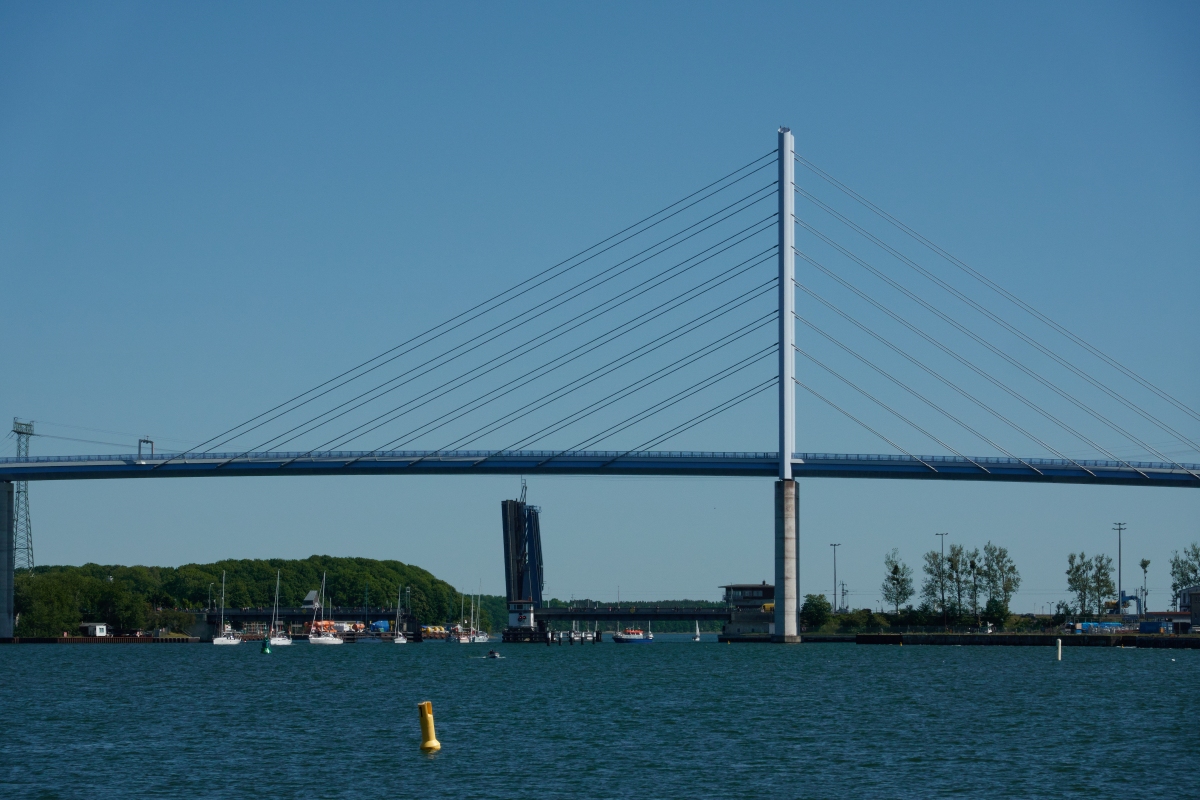
In a second step the shape of the 128 m high tower was very carefully optimized, because the tower exceeds the heights of the churches in Stralsund and dominates the city skyline from all directions. A wide variety of tower shapes were investigated from engineering and aesthetic points of view with regard to different load-bearing systems, different types of materials and different structural details until a convincing solution was arrived at. The selected tower, with a concrete substructure and a light upper steel part steel, dissolves the complete massive tower structure into two parts with the steel, avoiding the heaviness of a tower completely built from concrete. The beam, as a light cable-supported structure, is separated from the solid concrete substructure, including the upper steel tower, and this gives it a floating appearance.
Structural Details
A tear-shaped cross-section for all load-bearing members over the whole length of the bridge was introduced as common bridge characteristic. All piers were built as frames to improve their visual transparency. The tear-shaped cross-section was initially used for shaping with regard to the maritime surroundings. During the detailed design phase wind tunnel tests confirmed that this shape is also aerodynamically and structurally advantageous for the 128 m high tower. Aerodynamically shaped airfoil cross-sections which are traditionally used for vehicles and airplanes were rediscovered for large engineered structural components under high wind loads.
The piers with their uniform layout of two separate tear-shaped legs determine the overall appearance of the complete bridge which looks light and transparent in spite of its major dimensions.
The Cable-Stayed Bridge
Span lengths
The spans for the cable-stayed bridge are 198 m for the main span and 126 m for the side span. The main span length resulted from the navigational requirements, the location of the existing adjacent first Strelasund Crossing and the request not to expose the piers of the new bridge to possible ship collision.
Beam cross-section
The beam cross-section comprises an aerodynamically shaped, threecell steel box girder with an orthotropic deck. Its details are in accordance with modern requirements for fabrication, for example by using the same stiffeners for the top and bottom flange.
The wearing surface, with a total thickness of 8 cm, represents the state of the art. The deflection of the orthotropic deck under wheel loads was limited in accordance with the German codes in such a way that separation of the asphaltic surface from the orthotropic deck is prevented.
The usual ratio of 0.4 between side span and main span of cablestayed bridges results in uplift forces at the bridge ends.
These can be carried by steel pendulums or by a combination of bearings with tensioned cable hold-downs. Alternatively, the side span may be built in concrete. The span ratio of the Strelasund Crossing with 126/(2 × 198) = 0.32 results in a distinctly more advantageous situation due to the continuity of the bridge beam at both cable-stayed bridge ends.
The uplift forces from steel dead load and superimposed dead load are small: 460 kN/cable plane. The only significant upload forces are due to live load, temperature etc., and these result in 3100 kN/cable plane from live load. These can be counteracted with 520 m³ of regular concrete (23.5 kN/m³) and 50 m³ of heavyweight concrete (30.6 kN/m³). The ballast concrete with a total weight of 13 750 kN is distributed in the box girder over a length of 116 m, with a concentrated load at the hold-down axis.
The normal weight concrete not only acts as a counterweight but is connected with shear studs to the steel beam in composite action as a load-bearing part of the beam cross-section. During construction the concrete was placed in segments in order to provide the necessary counterweight for the free-cantilevering of the main span, and in order to equalize deviations of the steel deadweight.
Wind Barriers
Special attention was paid to the traffic safety on the bridge. At the high-level beam the increased wind speeds were taken into account for determining the lateral drag forces. It was shown by numerical simulation, as well as by wind tunnel testing, that the 1.5 m high glass cladding integrated into the railing provides sufficient wind shielding. It is thus expected that cars and loaded trucks can use the bridge even during strong winds. This was proven during the test phase before opening of the bridge by comprehensive measurements with the extensive instrumentation.
In order to rule out exposure of pedestrians beneath the bridge to crashing vehicles, a strengthened truck retaining system (German category H 4 b) is installed over the full cable-stayed length. The base plates for introducing the loads from the railing posts into the steel deck were mostly preinstalled in the shop.
In accordance with current German codes the strengthening was not strictly required because the road is only classified as ‘federal’, but it was permitted for this exposed situation by the German Federal Highway Authority at the instigation of the client DEGES. Later experiences with bridges along the A 71 ‘Thuringia Forest’ freeway as well as the A 20 ‘Baltic Sea Coast’ freeway proved the expedience of this measure.
Tower
The steel tower, which comprises two parallel vertical legs with tearshaped cross-section connected by three struts, rests on a concrete pier. The transition between steel towers and concrete pier was a demanding task.
The chosen solution – to fix the steel tower to the steel beam and support both on hinged bearings – was selected for aesthetic reasons. During detailed design, this solution with a visually separated beam also proved to be structurally and economically advantageous, for example because of the robustness against pier settlements and tiltings. The stiffening of the tower legs in the transverse direction required struts over their height.
Both legs of the steel tower are supported on Neopot bearings.
Stay Cables
The stay cables have a harp arrangement. The client promised in the official planning permit to increase the stay cable dia meters to at least 12 cm diameter to make the cables more clearly visible for the protection of the migrating birds. This would have required a substantial oversizing of locked coil ropes, which led to the first use of parallel-strand cables for a major German bridge. The tender documents detailed the generally licensed locked coil ropes, but included detailed additional specifications for contractors’ alternates for parallel-strand cables.
The parallel-strand system DYNA-Grip was accepted on this basis with a special license, based on an evaluation by the German Institute for Structural Design (DIBt). The experience from the comprehensive quality control program for the parallel-strand cables of this pilot project from fabrication to control measurements at the completed structure indicates that parallelstrand cables are at least equal to locked coil ropes with regard to corrosion protection, exchangeability, installation and economy.
Aerodynamic investigation
General
The Strelasund Bridge is the first German cable-stayed bridge designed in accordance with the new Eurocode. In 2001 the client DEGES provided an expert evaluation in agreement with the German Federal Highway Authority and the State of Mecklenburg-Vorpommern on the application of the Eurocode and its consequences for the required quantities.
Since wind loadings are not governing for most bridges they are covered rather globally in Appendix N. For example, the wind loads in accordance with Table N.1 are independent of the wind zone and the cross-section but only depend on the height above ground and the width-to-depth ratio of the beam. The longitudinal forces – for the first time in German codes – are also globally given with 25 % or 50 %, independent of the surface roughness of the beam, for example due to cross girders. For the wind-exposed Strelasund Bridge on the Baltic Sea coast 50 m above ground with aerodynamically shaped cross-sections of beam, towers and piers, detailed investigations were required.
Transverse Wind
For the protection of trailers and unloaded trucks from strong winds the already-mentioned installation of 1.5 m high wind barriers at both beam edges was decided when the detailed design was nearly completed. By numerical flow simulation and wind tunnel tests the influence of these wind barriers on the tilting moment of a 4 m high truck and on the loads of beam and piers was investigated.
The numerical calculations showed the shielding of the wind barriers. The tilting truck moment was reduced by about 50 %, which means the critical wind speed against tilting is increased by about 40 %.
Wind on Beam and Tower
An exact determination of the drag factor resulted in 20 % lower wind loads in spite of the wind barriers. This opens up a promising perspective for the retrofitting of other bridges. For the sizing of the wind barrier itself a drag factor of 1.7 was found, which resulted in a wind load of 3.67 kN/m² (50 m height, 59 m/second wind speed), significantly more than required by Eurocode.
A non-linear finite element calculation showed that 1.3 × 2.3 m composite glass safety panels made from 2 × 6 mm thick plates provide sufficient resistance. The non-linear calculation resulted in a decrease of stresses against a linear calculation of 87 % and a reduction of deflections of 55 %.
Superposition of longitudinal wind and temperature
DIN FB 101 provides different rules for superpositioning of wind and temperature:
- Appendix C.2.1.1 requires road bridges not to take into account wind and temperature simultaneously
- Appendix O.1 (2), however, requests to fully superimpose wind and temperature.
This coincidence of extreme temperatures with heavy storms is not expected at this bridge location. A combination factor of 0.6 was used. In this way the total movement at one roadway joint was reduced from 933 mm to 787 mm, which simplified the joints. (Meanwhile this contradiction in DIN FB 101 is omitted.)
Construction
Construction engineering
The beam was assembled from a total of 18 sections. The section lengths varied from 16.1 m to 95.3 m with weights between 145 t and 850 t. The sections were pre-assembled on the ground and lifted into position by a crawler crane or a floating crane. The erection started with four sections for the three approach spans on the Stralsund side.
The 128 m long side span of the main bridge acted as a side span of the continuous three-span approach girder without the stay cables in place. This construction stage did not govern the sizing. The main span was built by free cantilevering with 16.1 m long sections. The tower construction took place parallel to the beam erection and the installation of the stay cables.
The tower was subdivided into 15 segments (2 × 6 tower legs and three cross girders). After each newly installed beam section the corresponding forestay and backstay cables were installed. The biggest main span cantilever was 159.3 m. The two side spans on the Rügen side were crossed with three 50 m long sections.
For each individual erection stage the construction engineering provided the theoretical geometry and cable forces. Furthermore unit loadings for scaffolding, wind and temperature were precalculated in order to estimate the influence on site quickly. The deflections were systematically measured and listed numerically and graphically.
Construction of the Main Bridge
Substructure
The piers were founded on bore piles with 1.5 m diameter. In water they were built within sheet piles. For proof of the pile load-bearing capacity test loadings were executed on shore. The piers with their characteristic tear-shaped cross-section were built with jumping forms.
Side Spans
The beam sections of the side spans were pre-assembled in various lengths and lifted in. In order to interrupt the road traffic underneath the bridge as little as possible, some sections were installed at night. For the lifting of beam sections over water the floating crane, Taklift 7 was used.
The main span was constructed from full sections with the same floating crane Taklift 7 (capacity 500 t) and 1 750 t crawler crane. Most impressive was the installation of the 90 m long section with a total weight of 850 t. The beam tip at the tower was lifted with the floating crane, and at the land side a hydraulic strand jack resting on the already installed beam was used, Figs 1.162 and 6.163. The geometry required this section to be lifted with an angle of 13° until it could slide onto the tower pier.
Tower construction
The steel tower was also delivered in sections to the site, pre-assembled and lifted. The lower tower leg sections were lifted together with the first main span section. Then the remaining tower sections were lifted by the floating crane, and all sections were welded together in place.
Free Cantilevering of the Main Span
The main span was erected by free cantilevering. The pre-assembled sections were transported by barge and lifted with the floating crane.
The sections were then hung into a derrick located at the tip of the already erected beam. There they could be aligned precisely and welded. The floating crane would not have been steady enough for this purpose. The already installed beam was strong enough to support the new section without tie-backs. The welding of the new section took place under sheltered conditions from a traveler. After reaching the side span pier on the Stralsund side the steel beam installation was continued across the first side spans.
Cable Installation
The Strelasund Bridge was the first major German bridge to use parallel- strand cables. In accordance with international practice the cables were fabricated on site from their individual components and then the welded PE pipes were lifted by crane to the tower head with the lift cable attached to a temporary collar at its tip. The individual monostrands were then pulled into the PE pipe.
The wedges which clamp the monostrands into the anchor heads are pre-wedged at the passive tower head anchorage in order to prevent their slipping during the stressing from the active beam anchorage. The beam anchorages cantilever sideways out of the beam.
The monostrands were stressed individually with small monojacks to their theoretical force. The Isotensioning (Freyssinet) or ConTen (DSI) stressing system ensures that all strands reach the same final theoretical force.
The strands were stressed in stages with hydraulically coupled monostrands. In this way, all strands were stressed to the same force during the second stressing stage. This was not precisely possible during the first stressing stage because during the long period required for installing one strand after another, the temperature could vary considerably. Another advantage of stressing in two stages was that the second stage could be adjusted to the deflections of the beam during the first stage. This happened because the deflection behavior of the monolithic connection between beam and tower differed slightly from the design assumptions.
Corrective measures
Beam: The ballast concrete required against uplift in the beam at the anchor pier was structurally exploited in composite action to influence the deflections of the beam. In order to correct possible deviations from the theoretical geometry, a part of the concrete in the side span was only placed after the construction of the main span – including the superimposed dead loads – was completed.
Another possible corrective measure was the adjustment of the stay cable forces. When checking the deflections of the cantilever after installation of every new beam section an increase of 7 % of the deadweight was detected. This increase was confirmed by measuring the draft of the transportation barge. Consequently all cable forces were adjusted accordingly. Further adjustments were made to compensate small geometrical deviations during free cantilevering. The corresponding change in structural stresses was always checked and found to remain within the allowable range.
After completion of the steel erection the geometry at each cross girder was checked and no further corrective measures were required. Therefore, the remaining ballast concrete was placed in the box girder before all superimposed dead loads were applied.
Instrumentation: In order to account for the special loads and the structural innovations a detailed control and measuring program was installed. This permitted the control of the assumptions made for the detailed design during the period between completing the bridge and opening it for traffic. Also a database for the life of the bridge was assembled.
The measuring program comprises the load-bearing and stiffness behavior of the structure as well as the compilation of the climatic conditions for traffic guidance. For bridges of this size verification of the design assumptions are required because, for example, cable oscillations cannot be predicted precisely so that they may or may not occur.
The assumptions of DIN FB 101 with regard to superpositions of wind and temperature as well as the reduction of the wind loads found in wind tunnel tests against those stipulated were also checked by measurements.
The measuring was executed over a period of ten month before and after placement of the wearing surfaces, so that the influence of the asphalt on the temperature in the box girder and the eigendamping of the beam and the stay cables could be investigated.
All the data is centrally recorded in a computer. The results are downloaded by remote control and as well as the tuning of the individual installations. Initial records show that vertical oscillations are also excited by moderate wind speeds, but not in the transverse direction. A coincidence of strong winds and cable oscillations has not yet been observed.
Tower: The control measurements of the tower geometry showed only very small deviations within the tolerances.
Cable forces: At the end of the construction all cable forces were measured with hydraulic jacks by ‘lift-off-tests’. Taking into account the adjustments during construction, the cable forces varied only by ±5% against the theoretical values, which is within the measuring tolerances. Based on the results of the actual cable forces and the adjusted dead load the beam moments were recalculated, with the result that the changes corresponded with those already taken into account during construction. All stresses remain within the allowable limits, and a reduction of the partial load factor for permanent loads was not required. This would have been considered acceptable because the actual deadweight and the geometry were measured precisely.
Forces and geometry after completion: By precise planning of all construction stages and permanent controlling, including corrective measures for example due to deviations in the deadweight, it was ensured that at the end of construction all structural forces and the geometry coincided with the theoretical values. This is in accordance with the requirements of DIN FB 103, Section II-A.2.4 ‘Prestressing of structural elements’, which permits the use of the same partial load factors for the forces from ‘permanent loads acting on the elastic system’ and for the forces for ‘cable shortenings’.
In order to determine the stiffness of the beam, the tower and the stay cables static load tests were executed. The oscillation behavior of the beam in the main span was determined by dynamic drive tests of trucks across sleepers. The excitation and especially the decay spectrum were of interest. This test was repeated after placement of the wearing surfaces.
A continuous measurement of the oscillations for the longest seaward stay cables formed the basis for deciding whether additional damping against cable oscillation was required. During the design phase, structural preparations were made for the later installation of dampers near the cable anchorages at the beam. For this purpose, the horizontal and vertical cable accelerations were recorded at a point one tenth of the cable length away from the anchorage.
Whether parametric excitation can be identified as the cause of the cable oscillations can be determined with additional acceleration measurements at both ends of the cables. Dampers were installed afterwards on the four longest cables.
The influence of the wind on the cable oscillation was observed by a continuous recording of wind speed and direction. Wind sensors are installed at the footing of the tower pier (2 m above sea level), at the beam (about 44 m above sea level) and at the tower tip (128 m above sea level). This allows account to be taken of the influence of the topographical roughness on the vertical development of wind speed.
In addition to the permanent recording of the wind, the wind profile on the bridge deck before and after the installation of the wind barriers was measured. These measurements are to verify the theoretical investigations on the wind barriers. They also provide data on the wind forces during the operation of the bridge and thus form the basis for the decision when to close the bridge during strong winds.
The deflections due to temperature and longitudinal wind are measured at both roadway joints in order to confirm the applied combination factor. The outside temperature is measured with a temperature sensor in the tower axis. The steel temperature at the top and bottom flange is measured in the center of the main span. In addition, the air tempera ture inside the box girder is also recorded. The temperature records will provide a correlation between the movements of the roadway joints and of the top and bottom flange temperatures of the box girder after placement of the wearing surface.
Excerpt from: Svensson, Holger Cable-Stayed Bridges, Wilhelm Ernst & Sohn Verlag für Architektur und technische Wissenschaften GmbH, Berlin (Germany), ISBN 343302992X; pp. 369-386. References to figures and literature were omitted.
Participants
- André Keipke (architect)
- Büchting + Streit B+S Beratende Ingenieure VBI
- Schmitt Stumpf Frühauf und Partner Ingenieurgesellschaft im Bauwesen mbH

- Peter Otte (checking engineer) (BW 1.1)
- Ulrike Kuhlmann (checking engineer) (BW 1.2)
- Reiner Saul (checking engineer) (BW 2)
- Winfried Koldrack (checking engineer) (BW 3-5)
- Hans-Peter Andrä (checking engineer)

Relevant Web Sites
There currently are no relevant websites listed.
Relevant Publications
- (2007): Brücken in Deutschland II. für Straßen und Wege. Deutscher Bundes-Verlag, Cologne (Germany), ISBN 978-3-935064-46-0, pp. 164-165.
- Brücken und Tunnel der Bundesfernstraßen 2008. Deutscher Bundes-Verlag, Cologne (Germany), ISBN 978-3-935064-54-5, 2008, pp. 7-34.
- (2013): Cable-Stayed Bridges. 40 Years of Experience Worldwide. Wilhelm Ernst & Sohn Verlag für Architektur und technische Wissenschaften GmbH, Berlin (Germany), ISBN 978-3-433-02992-3, pp. 369-386.
- DYNA Grip® Schrägseile für neue Ziegelgrabenbrücke. Ziegelgrabenbrücke, 2. Strelasundquerung, Stralsund – Insel Rügen, Deutschland. In: DSI Info, n. 14 ( 2006- 2007), pp. 36-37.
- DYNA Grip® Stay Cables for new Ziegelgraben Bridge. Ziegelgraben Bridge, 2nd Strelasund Crossing, Stralsund - Rügen Island, Germany. In: DSI Info, n. 14 ( 2006- 2007), pp. 36.
- About this
data sheet - Structure-ID
20005155 - Published on:
18/09/2002 - Last updated on:
12/07/2021


