
General Information
Project Type
| Structure: |
Tied-arch bridge |
|---|---|
| Function / usage: |
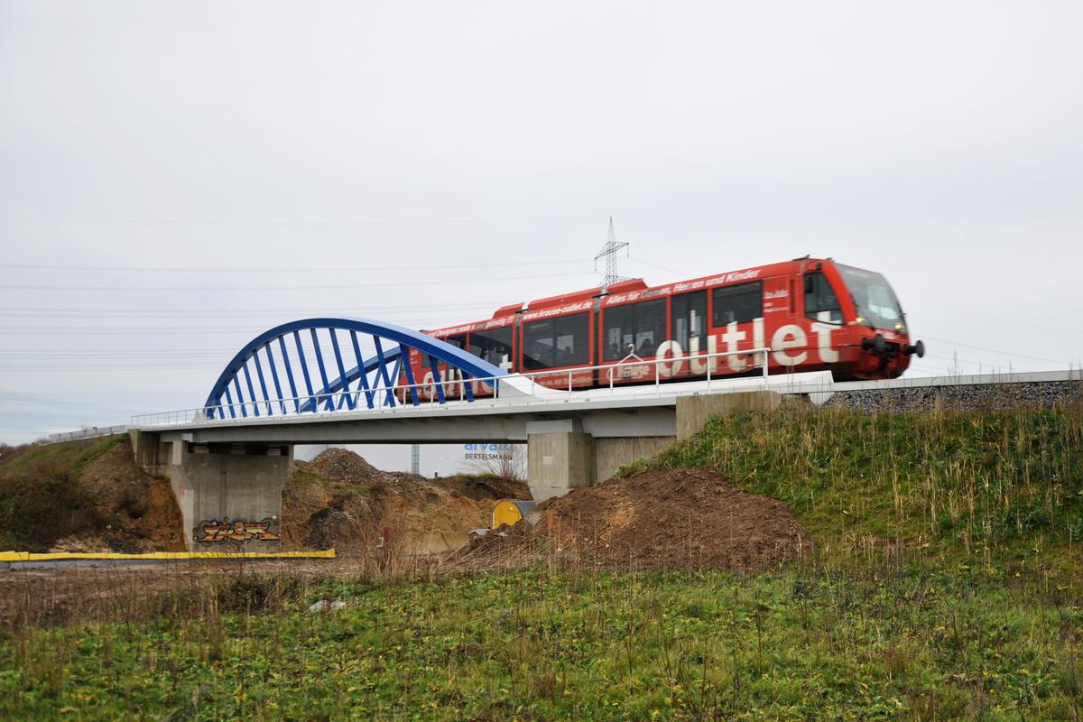
Railroad (railway) bridge |
| Material: |
Steel-prestressed concrete composite bridge |
Awards and Distinctions
| 2013 |
entry
for registered users |
|---|
Location
| Location: |
Düren, Düren (Kreis), North Rhine-Westphalia, Germany |
|---|---|
| Crosses: |
A 4 Motorway (Germany)
|
| Coordinates: | 50° 50' 30.53" N 6° 27' 54.97" E |
Technical Information
Dimensions
| total length | 59.55 m | |
| span | 38.80 m | |
| deck width | 8.49 m | |
| horizontal radius of curvature | ∞ | |
| longitudinal slope | 0.9 % | |
| crossing angle | 92 gon | |
| arches | rise | 4.782 m |
| cross-sectional dimensions | 0.50 m x 0.40 m | |
| deck | walkway width | 2 x 1.00 m |
Quantities
| abutments | concrete volume | 315 m³ |
| reinforcing steel | 60 t | |
| reinforcing steel content | 2.40 % | |
| superstructure | structural steel | 130 t |
| concrete volume | 127 m³ | |
| prestressing steel | 12 t | |
| reinforcing steel | 25 t | |
| reinforcing steel content | 3.70 % |
Design Loads
| live load | UIC 71 | |
| live load | UIC 71; SW | |
| design code(s) | DIN Fachbericht |
Materials
| deck |
prestressed concrete
(C 45/55)
|
|---|---|
| arches |
steel
(S 355 ML)
|
| suspenders |
steel
(S 235 JR)
|
| abutments |
reinforced concrete
|
| cross beams |
steel
(S 355 ML)
|
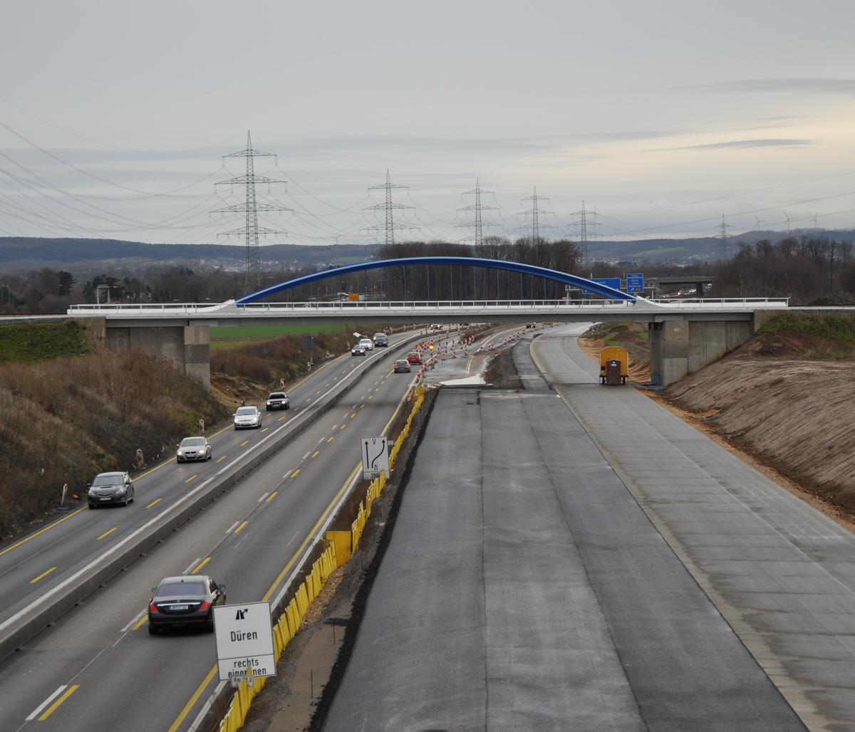
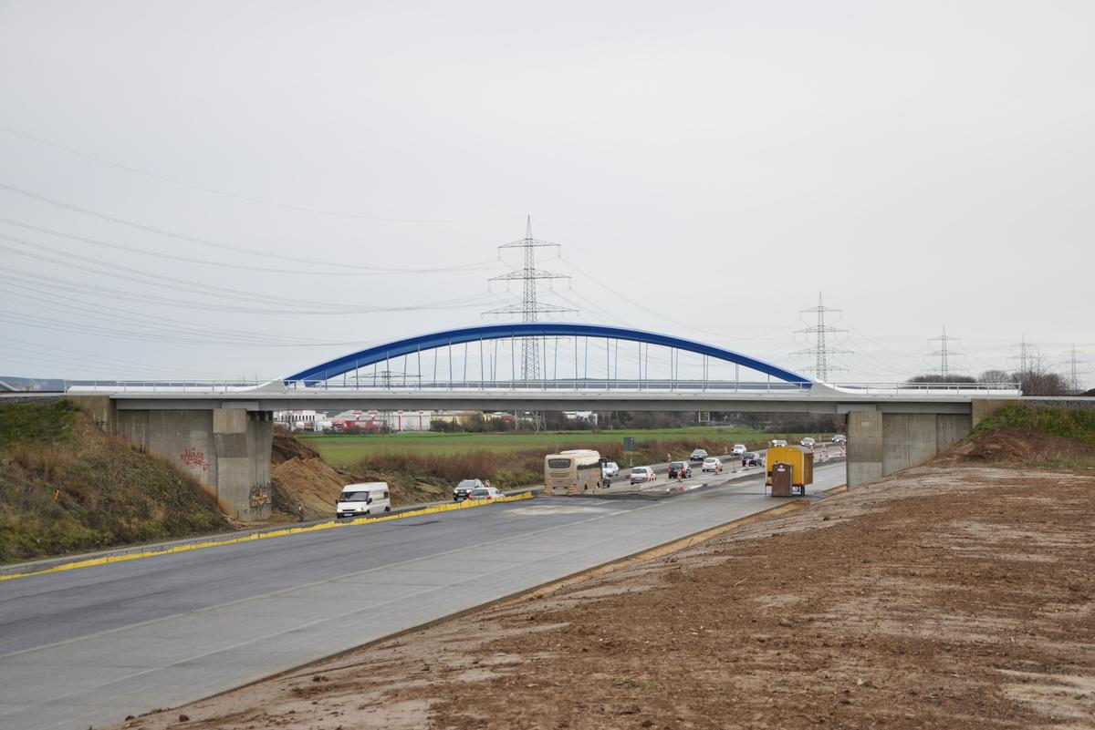
New construction of the railroad overpass over the BAB 4 at km 11.246 of the line Düren - Linnich
The railroad overpass of the Rurtalbahn line Düren – Linnich over the BAB 4 Cologne – Aachen in the district of Düren, was replaced by a new structure. The new construction was necessitated by the six-lane expansion of the BAB 4 between the Düren and Kerpen interchanges and the associated relocation of the route through the expansion of the Hambach open-pit lignite mine.
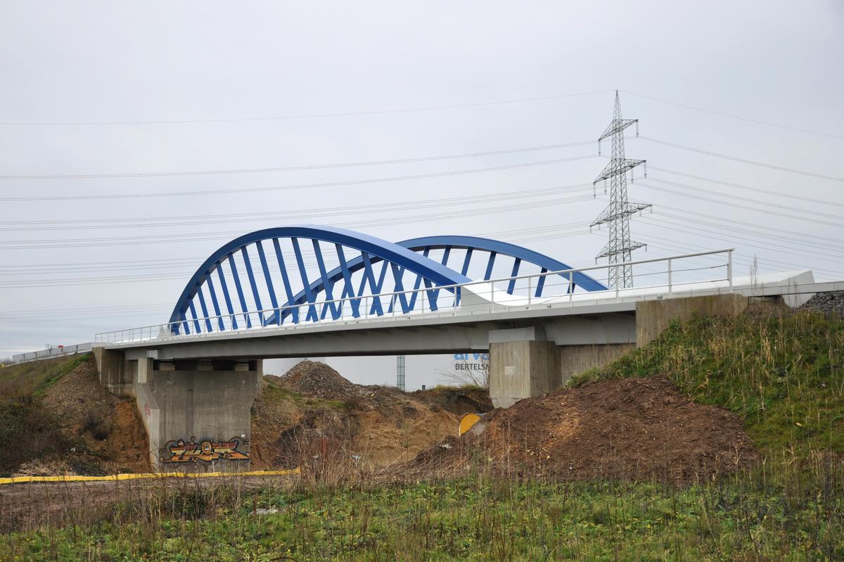
Major constraints from the routing and specifications from the railroad operator led to the planned appearance of the bridge. A construction without center support was to be chosen, on the one hand to exclude vehicle impact, and on the other hand to counteract constraints from different settlements by a statically determined bearing in the event of an uneven rise in groundwater to be expected in the future after excavation of the Hambach opencast lignite mine. Due to the defined gradients of the BAB 4 and the railroad line, a maximum construction height below the track of only 0.50 m is possible. It was not possible to raise the railroad gradient because of the modifications this would require at neighboring stopping points. The structure is designed in accordance with DIN Technical Report 101 for loading by the UIC 71 load model. According to DIN 4149:2005-04, the structure is located in seismic zone 3, with the strongest seismic load in the application area of the standard. The structure is designed for this seismic loading.
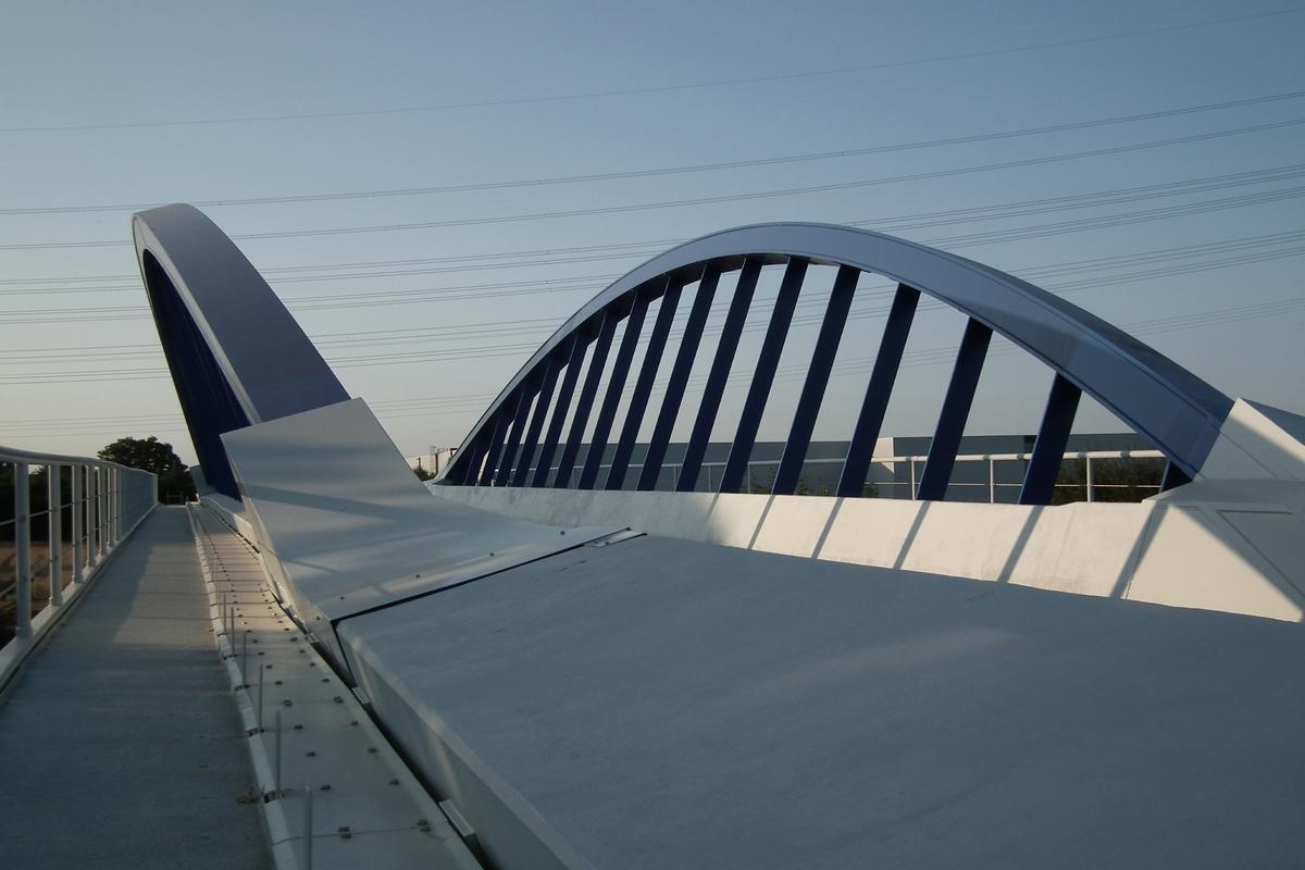
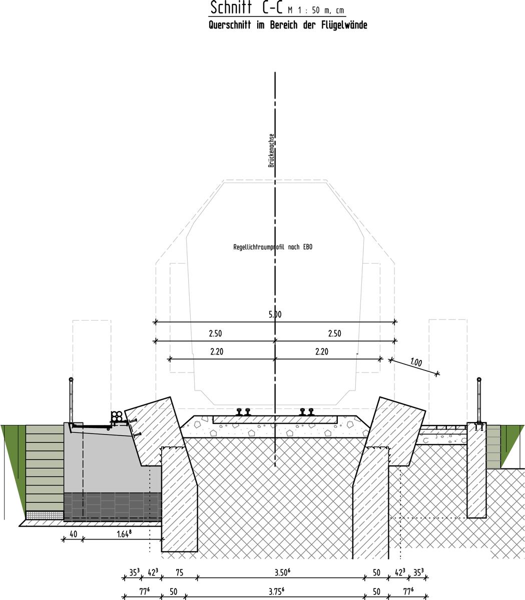
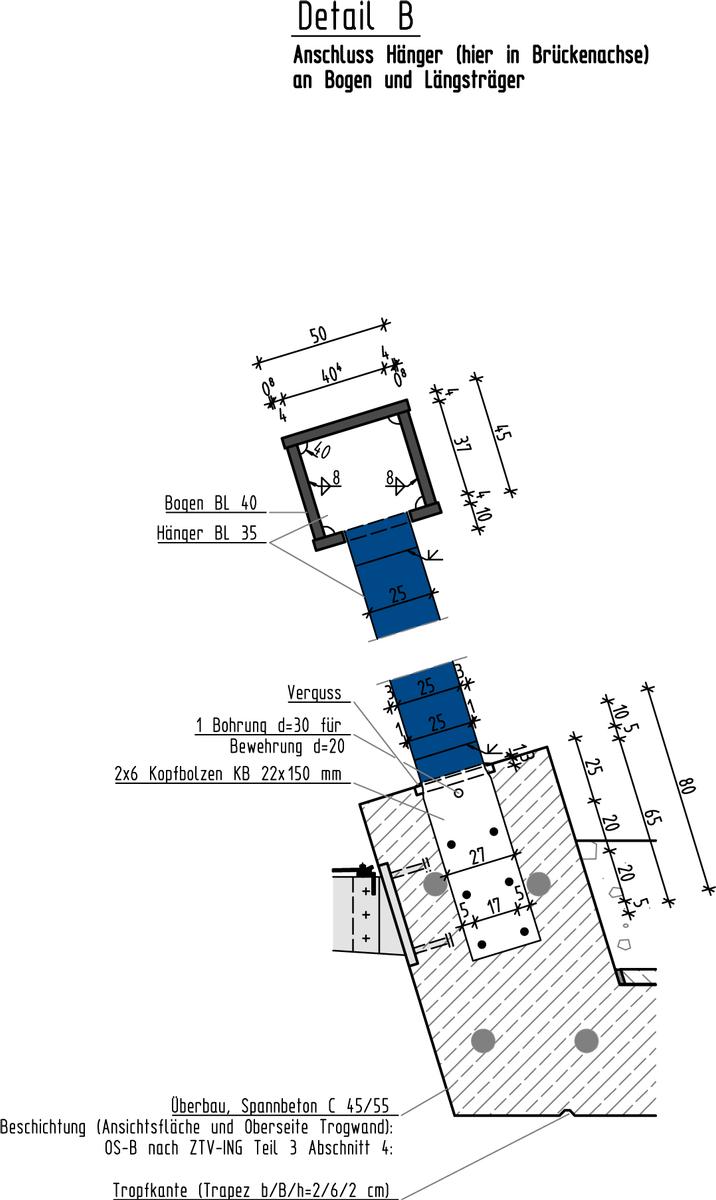
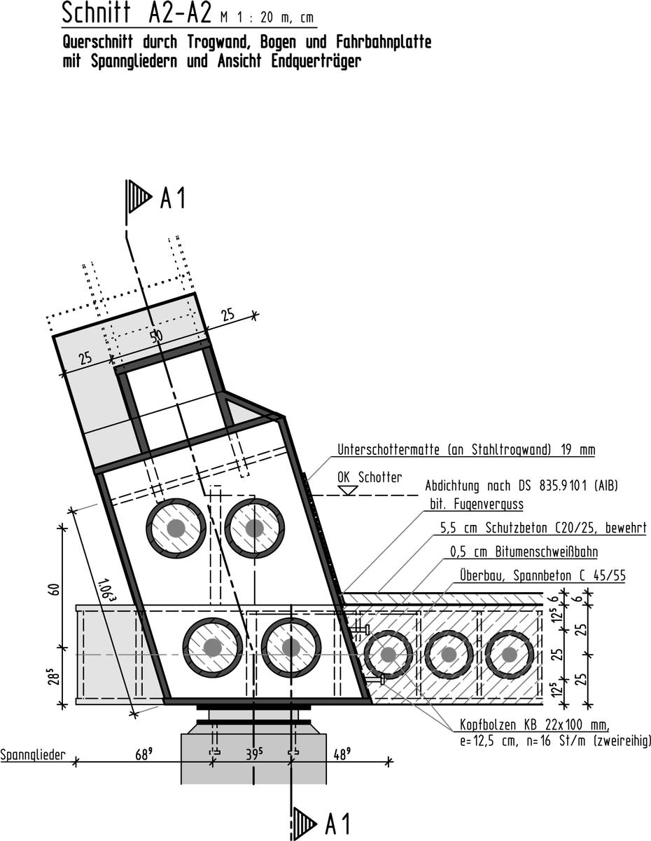
The available construction height between the upper edge of the clearance profile above the BAB 4 and the elevation of the gradient of the Rurtal railroad was only 0.50 m after deduction of the track bedding. Only a prestressed concrete trough could be considered as the carriageway structure. In order to make the trough walls transparent, they were designed above the track bed as a bar arch on which the prestressed concrete trough was suspended. The height restriction of the trough floor allowed a maximum outer trough width of 5.35 m in order to comply with the bending stresses in the transverse direction of the superstructure. This would not have made it possible to maintain the clearance of 5.00 m width, which is also required in particular in the bridge area due to necessary oversize goods transports. Instead, two bar arch structures inclined outward by 17° were arranged at the trough edges. The steel arches consist of welded rectangular hollow sections of 500 x 450 mm with hanging bars of flat bars 35 x 250 mm, which were spaced at 2.00 m intervals. The chosen arch inclination allows the required clearance on the superstructure. The bar arches were clamped in steel end cross girders for anti-tilting at the end supports. These end cross beams are made of multi-cell welded rectangular box girders 1540 x 500 mm. The tendons are guided by the box girder which has been stiffened by thick-walled tubes.
The carriageway-bearing reinforced concrete trough with a bottom slab of 0.50 m and trough sides also 0.50 m thick was prestressed between the end cross girders and suspended from the hanging bars. In the area of the transition of the bar arch into the trough cross-section, the trough sides and the arch are widened to a width of 1.00 m to provide sufficient space for the required anchoring of the prestressing. The clear width of the bridge is 2 x 18.25 m according to the planning approval decision. Despite the ground plan inclination of 92 gon, the structure will be built as a right-angled crossing in order to exclude an offset of the arches in longitudinal direction. This results in a clear width of 37.80 m and a span of 38.80 m.
The roadway trough structure was made of prestressed reinforced concrete. The lateral trough surface, which is in the same plane as the steel structure in the arch-fighter area, is formed from smooth slabs to give off a uniform appearance. The rest of the reinforced concrete superstructure will be given a rough board structure.
The track will receive a bearing on the superstructure in the ballast bed. Under ballast mats have been arranged to reduce noise emissions.
The prestressed concrete trough was made of concrete C 45/55. The prestressing was made of 1570 / 1770 steel, reinforcement of BSt 500 S(B) steel, the steel structure of S355ML steel for the arch and end cross girder structure and S 235 JR for the other structural parts. The bar arch and suspension bars were painted in 5010 blue. On both sides of the trough structure, a service road with a walkway width of 0.80 m and a cable trough route are arranged within the cantilever below the inclined arch structure. The cantilever construction consists of steel profiles spaced at the distance of the arch hangers, the tread was made of GRP sheets.
The lateral termination of the superstructure is formed by railings made of a post - handrail construction with a rope filling. The height of the handrail above the sidewalk is 1.00 m.
The railing was made of steel grade S 235 JR G2 with a corrosion protection system in accordance with ZTV-KOR steel structures with a top coat in color 7035 light gray. The handrail is made of steel 1.4571, the surface is brushed.
Due to the magnitude of the existing bearing forces and displacements, deformation bearings were chosen as an economical, durable and easy-to-maintain solution. Braking, wind and lateral forces are absorbed by a fixed bearing and a transversely fixed bearing on the abutments by means of stop structures.
A replacement of all bearings is possible.
Since the superstructure bearing allows all expansions and displacements to continue from the northern abutment, deck transitions are provided at both ends of the bridge, which were designed according to type T-40 in accordance with S-FGK 22 for a maximum expansion distance of 57 mm. The bridge was provided with a waterproofing consisting of a bituminous welded membrane with a 55 mm thick protective concrete layer. In the course of the track construction work, the ballast bed and the track on the bridge will be built.
The entire steel structure received corrosion protection in accordance with ZTV-Kor Stahlbauten. The entire reinforced concrete surface of the abutments and the superstructure were provided with a hydrophobic coating (system OS-A) in accordance with ZTV-ING Part 3 Para. 4 (8) to protect against de-icing salt attack, as the structure will be taken under traffic immediately after completion.
The abutments were built as box-shaped reinforced concrete structures consisting of a foundation slab, the abutment wall with lateral additions to accommodate the chamber walls, and the wing walls. To achieve a continuous transition from the trough cross-section to the embankment fill, the wing walls were placed in the trough side elevation in plan. The service roads cantilever to the rear of the wing walls and are brought into the embankment position by wing side additions. The abutments and wing walls were constructed in reinforced concrete of strength class C 30/37. Reinforcing steel grade BSt 500 S (B) was installed as reinforcement. All visible surfaces were given a rough board structure. The shallow foundation under the abutments consists of a 0.80 m thick foundation slab made of concrete C35/45 with a width of 6.40 m and lengths of 8.40 m on the north side and 8.70 m on the south side for each abutment side.
The construction work was carried out while traffic on the BAB 4 was maintained. Only during the assembly of the arch structure and the erection and dismantling of the falsework, short-term full closures of the BAB 4 will be necessary.
Explanatory report on the submission for the engineering construction award 2013 of the engineering office Dipl.-Ing. Lorenz Cornelissen
.
Participants

Relevant Web Sites
There currently are no relevant websites listed.
Relevant Publications
- (2014): Eisenbahnbrücken. Wilhelm Ernst & Sohn Verlag für Architektur & technische Wissenschaften GmbH & Co. KG, Berlin (Germany), ISBN 978-3-433-03097-4, pp. 104.
- (2011): Elegant und funktional. Ein außergewöhnlicher Ingenieurbau: Die neue Eisenbahnüberführung über die A4 zwischen Düren und Linnich. In: Deutsches Ingenieurblatt, v. 18, n. 7-8 ( 2011), pp. 28-30.
- About this
data sheet - Structure-ID
20064313 - Published on:
13/11/2012 - Last updated on:
29/04/2021


