


General Information
| Name in local language: | Viaduc de Millau |
|---|---|
| Beginning of works: | 16. Oktober 2001 |
| Completion: | 14. Dezember 2004 |
| Duration of works: | 38 months |
| Status: | in Nutzung |
Project Type
| Structure: |
Mehrfeldrige Schrägseilbrücke Schrägseilbrücke mit Mischsystem |
|---|---|
| Support conditions: |
for registered users |
| Secondary structure(s): |
Structurae Plus/Pro - Subscribe Now! Structurae Plus/Pro - Subscribe Now! |
| Function / usage: |
Autobahnbrücke |
| Material: |
Stahlbrücke Structurae Plus/Pro - Subscribe Now! Structurae Plus/Pro - Subscribe Now! |
| Plan view: |
Structurae Plus/Pro - Subscribe Now! |
| Construction method: |
Fahrbahntafel: Längsverschub mit temporärer Abspannung Pfeiler: Kletterschalung |
Awards and Distinctions
| 2006 |
Preisträger
for registered users |
|---|---|
|
for registered users |
Location
| Location: |
Millau, Aveyron (12), Occitanie, Frankreich Creissels, Aveyron (12), Occitanie, Frankreich |
|---|---|
| Address: | A 75 |
| Trägt den/die: |
|
| Überquert: |
|
| Part of: | |
| Neben: |
Centre d'information du viaduc de Millau
|
| In der Nähe von: |
Mautstation des Millau-Viadukts (2004)
|
| Coordinates: | 44° 5' 6" N 3° 1' 18" E |
Technical Information
Dimensions
| Gesamtlänge | 2 460 m | |
| Stützweiten | 204 m - 6 x 342 m - 204 m | |
| Anzahl Felder | 8 | |
| Horizontaler Krümmungsradius | 20 000 m | |
| Fahrbahntafel | Überbauhöhe | 4.20 m |
| Höhe über Talgrund oder Wasser | 270 m | |
| Gesamtbreite | 32.050 m | |
| Längsneigung | 3.025 % | |
| Pfeiler P1 | Höhe | 94.50 m |
| Pfeiler P2 | Höhe | 244.96 m |
| Pfeiler P3 | Höhe | 221.05 m |
| Pfeiler P4 | Höhe | 144.21 m |
| Pfeiler P5 | Höhe | 136.42 m |
| Pfeiler P6 | Höhe | 111.94 m |
| Pfeiler P7 | Höhe | 77.56 m |
| Pylone | Höhe des Pylonen (über Fahrbahn) | 88.92 m |
| Höhe des Pylonen (über Grund) | max. 343 m |
Quantities
| Volumen der Erdarbeiten | 350 000 m³ | |
| Baubehelfe | Baustahl | S 355: 3 200 t S 460: 3 200 t |
| Betonvolumen | 7 500 m³ | |
| Betonstahl | 400 t | |
| Fahrbahntafel | Baustahl | S355: 23 500 t S460: 12 500 t |
| Fundamente | Betonstahl | 13 450 t |
| Fundamentplatten | Betonvolumen | 13 000 m³ |
| Betonstahl | 1 300 t | |
| Pfähle | Betonvolumen | 6 000 m³ |
| Betonstahl | 1 200 t | |
| Pfeiler | Betonvolumen | 53 000 m³ |
| Spannstahl | 200 t | |
| Betonstahl | 10 000 t | |
| Pylone | Baustahl | S355: 3 200 t S460: 1 400 t |
| Schrägseile | Stahl für Schrägseile | 1 500 t |
Cost
| Baukosten | Euro 300 000 000 |
Materials
| Fahrbahntafel |
Stahl
|
|---|---|
| Pfeiler |
Stahlbeton
|
| Pylone |
Stahl
|
| Widerlager |
Stahlbeton
|
| Schrägseile |
Stahl
|
| Pfeilerköpfe |
Spannbeton
|
Chronology
| 1987 | Erste Trassierungsvorschläge durch das CETE Aix-en-Provence. |
|---|---|
| 1990 | Das zuständige Ministerium fällt eine Entscheidung zugunsten einer Tarnquerung von etwa 2500 Metern. |
| 1993 — 1994 | Sieben Architekten und acht Ingenieurbüros werden separat konsultiert. |
| 1995 — 1996 | Zweite Studienphase zur Formfindung mit fünf Entwurfsgruppierung mit jeweils einem Architekten und einem Ingenieurbüro. |
| 1996 | Die Jury entscheidet sich für die Lösung mit der mehrfeldrigen Schrägseilbrücke der Entwurfs-ARGE Sogelerg - Norman Foster. |
| 1998 | Es wird entschieden, den Viaduc de Millau in einem Konzessionsmodell zu betreiben. |
| 2000 | Wettbewerbsbeginn für die Konzession/den Bau. |
| März 2001 | Eiffage gewinnt den Wettbewerb und wird zum Konzessionär erklärt. |
| Mai 2001 | Der Bauvertrag wird unterschrieben. |
| August 2001 | Die Konzession wird vom Ministerium an Eiffage vergeben. |
| 16. Oktober 2001 | Baubeginn. |
| November 2002 | Pfeiler P2, der am höchsten werden soll, wächst auf über 100 Meter an. |
| 26. 2003 | Das Einschieben des Überbaus beginnt. |
| 28. Mai 2003 | Pfeiler P2 übersteigt die Höhe von 180 Metern und wird dadurch der höchste Brückenpfeiler der Welt, ein Rekord der vorher vom Kochertalviadukt gehalten wurde. Der Rekord wird vermutlich bis zum Jahresende nochmals gebrochen - der höchste Pfeiler soll 245 Meter hoch sein. |
| 3. Juli 2003 | Beginn der Verschubphase L3. Sie endet 60 Stunden später. Am Ende des Verschubes wird der Fahrbahnträger vorübergehend "festgenagelt", um die Standfestigkeit bei Windstärken bis zu 185 km/h zu gewährleisten. |
|
25. August 2003
— 26. August 2003 |
Verschubphase L4. |
| 12. September 2003 | Zweite Verschubphase (L2) des nördlichen Fahrbahnträgers auf 114 Meter Länge. Der erste Verschub (L1) wurde quasi auf dem Trockenen hinter dem Widerlager geübt, um die technischen Vorrichtungen zu testen und zu justieren. |
| November 2003 | Fertigstellung der Pfeiler. |
| 26. März 2004 | Verschubphase L10 von der Südseite. Der Stahlhohlkasten erreicht den Pfeiler P3. |
|
Nacht vom 4. April 2004
— 5. April 2004 |
Der Stahlträger des Überbaus wird auf den Pfeiler P2 geschoben, dem höchsten Brückenpfeiler weltweit. Der Verschub wird dabei durch Wind und Nebel verlangsamt, die das Laserführungssystem stören. Zu diesem Zeitpunkt sind insgesamt 1 947 Meter des Überbaus eingeschoben. |
| 20. April 2004 | Ende des Verschubs des Überbaus von der Nordseite. Das Ende des Hohlkastens ragt bis zur Feldmitte über den Pfeiler P2 hinaus. Es verbleiben noch 2 Verschubphasen von der Südseite aus. |
| 28. Mai 2004 | Fertigstellung des Fahrbahnträgers. |
| Ende Juli 2004 | Fertigstellung der Pylone. |
| November 2004 | Vorgesehene Fertigstellung der Demontage der Hilfsstützen. |
| 17. November 2004 | Beginn der Belastungsproben mit einer Gesamtlast von 920 Tonnen. |
| 14. Dezember 2004 | Eröffnung durch den französischen Staatspräsidenten Jacques Chirac. |
| 16. Dezember 2004, 09:00 | Verkehrsfreigabe. |
| 2006 | Outstanding Structure Award 2006 (IABSE) |
Weitere technische Details
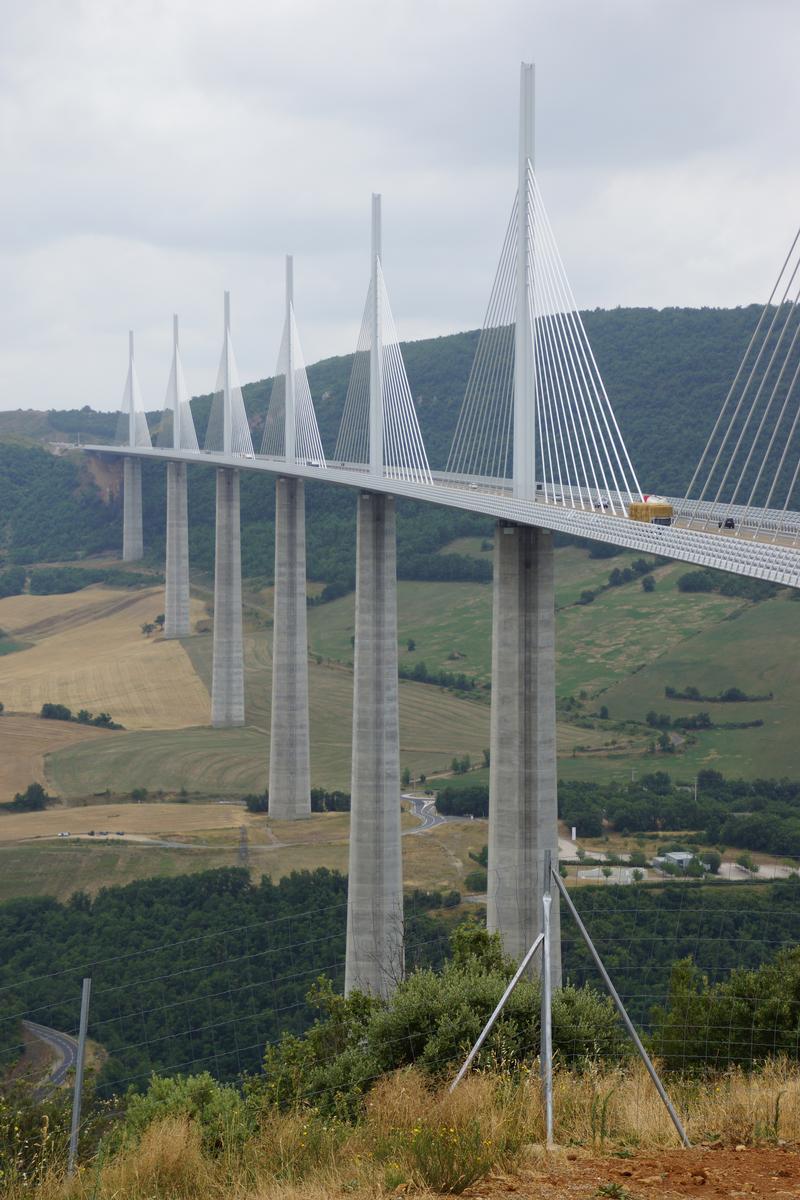
Pfeiler
Die Pfeiler haben folgende Abmessungen:
- In Längsrichtung: 16 bis 17 Meter
- In Querrichtung: Variabel beginnend mit 10 Metern am Pfeilerkopf und bis zu 27 Metern am Fuß für den höchsten Pfeiler
Die Pfeiler teilen sich in zwei Arme 90 Meter unter der Fahrbahn. Die Arme sind vertikal vorgespannt mit jeweils acht Spannsträgen 19T15S.
Die Abmessungen der Arme ist ebenfalls variabel: In Längsrichtung 5 Meter am Kopf und 8,60 Meter am unteren Ende.
Bei Fertigstelltung der Brücke waren die Pfeiler die höchsten jemals erbauten Brückenpfeiler der Welt und mit den Pylonen zusammen sind sie höher als der Eiffelturm.
Pylone
Die Höhe der Pylonen beträgt insgesamt 87 Meter. Die Form entspricht einem invertierten Y in der Längsrichtung. Die Höher der Beine dieses Y ist 38 Meter.
Jeder Pylon hat ein Gewicht von 650 Tonnen und eine Höhe von nahezu 89 Metern. Die Pylonen werden hinter den Widerlagern zusammengeschweißt, und schließlich in waagerechter Lage in einem Stück auf einem Kamag-Transporter zum entsprechenden Pfeiler transportiert. Dort werden Sie im Laufe eines halben Tages mit einer Hilfsvorrichtung in die Vertikale gedreht.
Abspannung.
Die Fahrbahn wird mit Schrägseilen abgespannt. Diese sind in zwei Ebenen angeordnet zu je 11 Schrägseilen. Die Verankerungen der Schrägseile haben einen Abstand von 12.51 Metern im Fahrbahnträger.
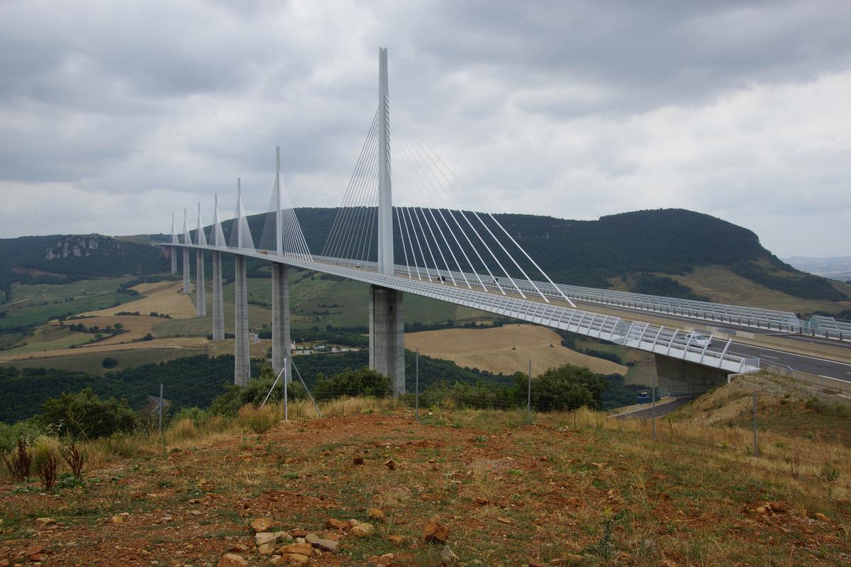
Entwurf und Bau des Viaduc de Millau
Am 16.12.2004 wurde das große Viadukt von Millau dem Verkehr übergeben und damit die letzte Lücke in der zweiten französischen Nord-Süd-Verbindung A 75 geschlossen. Den Namen Rekordbrücke hat sie wahrlich verdient, nicht nur ist sie die höchste Brücke der Welt, die den Fluss Tarn in einer Höhe von 270 m überquert, sondern auch die Bauzeit von 38 Monaten und die Kosten (ca. 400 Mio. €) sind durchaus rekordverdächtig. Dabei begannen die Planungen für dieses Ausnahmeprojekt schon Ende der 1980er Jahre. Da die klassische französische Nord-Süd-Verbindung A7 durch das Rhône-Tal in den Sommermonaten ständig überlastet ist, lag der Gedanke nahe, eine zweite Verbindung zu installieren – quer durch das Gebirge Massif Central im Herzen von Frankreich. Dabei gab es vor allem ein natürliches Hindernis: das weite Tal des Flüsschens Tarn in der Nähe des Städtchens Millau – bekannt vor allem durch seine schier unendlichen Verkehrsstaus im Sommer. So entschied man sich, durch ein 2.460 m langes Viadukt das Tal zu überbrücken. 1996 beschloss man, eine Reihe von Schrägkabelbrücken zu bauen. Konstruktion und Betrieb des Projektes wurden dabei in einem Konzessionsverfahren durchgeführt; die Konzession endet 78 Jahre nach Baubeginn. Insgesamt wird mit einer Gesamtnutzungsdauer von 120 Jahren gerechnet. Das Ziel war, die Bauzeit zu verkürzen und damit frühzeitig auf die Mauteinnahmen zugreifen zu können. Dies veranlasste den französischen Baukonzern Eiffage zusammen mit seiner Tochter Eiffel Construction Métallique, gegen den ursprünglichen Entwurf einer vorgespannten Betonbrücke eine Alternative mit Stahlbalken und Stahlpylonen vorzustellen. Diese Lösung wurde im März 2001 ausgewählt und mit den Bauarbeiten im Oktober 2001 begonnen. Vorteile der Stahllösung gegenüber der Betonlösung sind:
- Leichtigkeit und Schlankheit des Fahrbahnträgers (36.000 t gegen 120.000 t in Beton),
- Verringerung der Bauhöhe des Fahrbahnträgers auf 4,20 m (geringere Windanfälligkeit),
- Sicherheit: Verringerung der notwendigen Arbeitsschritte in der Höhe durch Vormontage und Taktschiebeverfahren,
- Minimierung der Anzahl der Schrägseile sowie der Fundamentierung,
- Verringerung der Gesamtkosten des Projekts (maßgeblich).
Innerhalb von 2,5 Jahren wurden fast 43.000 t Stahl für das Fahrbahndeck, die Pylonen und die Montagehilfsstützen verarbeitet. Während der gesamten Entwurfsphase war Michel Virlogeux der maßgebliche Ingenieur für die französische Autobahnbehörde SETRA, während der Bauphase beriet er maßgeblich die Bauausführung.
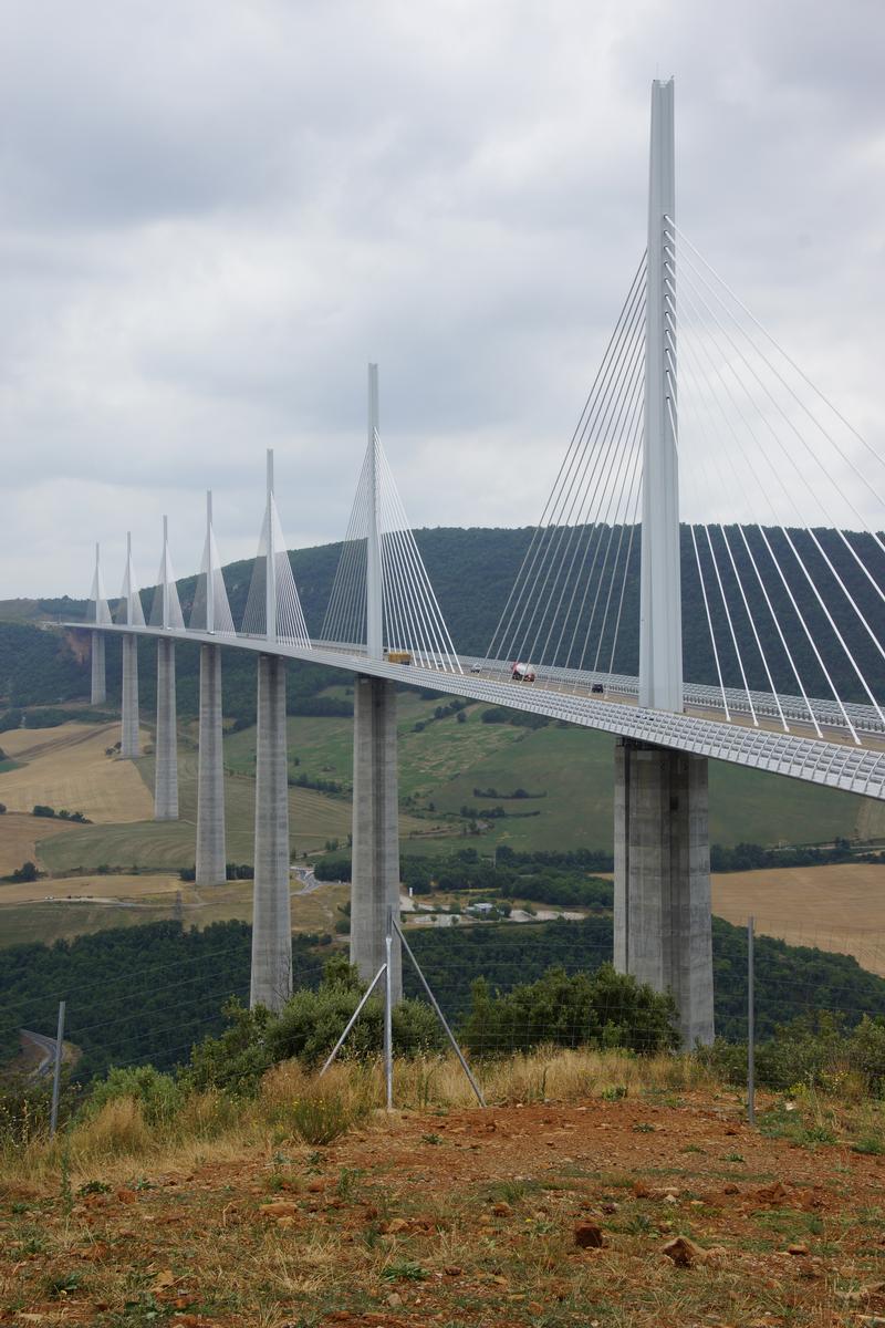
Entwurf
Die Millau Brücke hat eine Gesamtlänge von 2.460 m und umfasst 8 Spannweiten, 2 Seitenspannweiten mit 204 m und 6 innere Spannweiten mit 342 m. Der Querschnitt besteht aus einem Stahlhohlkasten mit orthotroper Fahrbahn, zwei vertikalen inneren Trägern und schrägen seitlichen Unterflächen. Die Stege sind für die Herstellung im Taktverschiebeverfahren erforderlich, die dreieckigen Randträger schaffen einen stromlinienförmigen Querschnitt, der die Windlasten auf das Bauwerk reduziert. Außen auf dem Balken sind Windabweiser installiert, die ein Umkippen von hohen Lastwagen verhindern sollen. Die Ausrundungen beider Brückenseiten verbessern das aerodynamische Verhalten und das Aussehen. Wegen der großen Höhe über dem Tal war eine Mittelträgerösung mit nur einer Kabelebene sinnvoll. Der Hohlkasten liefert die dafür erforderliche Torsionssteifigkeit des Balkens. Maßgeblich für den Entwurf der Brücke war die Forderung, dass die bis zu 244 m hohen Pfeiler steif genug sind, um in Längsrichtung unsymmetrische Lasten aufzunehmen. Andererseits müssen sie weich genug sein, um den Längsverformungen des Balkens aus Temperatur folgen zu können. Die Lösung besteht in einem kräftigen Hohlkastenquerschnitt an der unteren Einspannung, der unterhalb des Balkens vertikal geschlitzt ist. Die Auflösung des geschlossenen Querschnitts verschafft die nötige Biegeweichheit. Die 87 m hohen Pylonen oberhalb der Fahrbahn sind als steife A-Böcke in Brückenlängsrichtung ausgebildet. Die gespreizten Stiele der Pylonen treffen am Balken auf die ebenfalls gespreizten zwei Stiele der Pfeiler. Es entsteht so ein Gesamtsystem aus Pfeiler + Pylon, das das an der Pylonspitze aus exzentrischen Lasten angreifende Moment in vertikale Zug- und Druckkomponenten zerlegt. Die geteilten, 90 m langen Pfeilerschäfte wurden vertikal vorgespannt, um den Zugspannungen aus Wind auf die mittleren Pfeiler und aus Temperaturschwankungen auf die Randpfeiler entgegenzuwirken. Zwischen Stahlüberbau und Betonpfeiler befinden sich vier Lager, die gegen Abheben in die Pfeilerschäfte vorgespannt sind. Unter unsymmetrischen Lasten und extremem Wind beträgt die Druckkraft auf jedem Lager bis zu 100 MN. Dafür wurden neuartige Kalottenlager eingesetzt. Der Pylon oberhalb des Überbaus ist aus Stahl, um so leicht und so schlank wie möglich zu sein. Die mittlere Kabelebene ist zwischen den längslaufenden äußeren Blechen verankert.
Herstellung
Pfeiler
Die Pfeiler haben zwar veränderliche Querschnitte, die Abmessungen wurden aber so gewählt, dass sie einfach zu schalen waren. Vier Seiten haben unveränderliche Abmessungen, und die anderen vier ändern sich gleichmäßig in jedem Bauabschnitt. Dieses erlaubte die Herstellung mit äußerer Kletterschalung und innerer Schalung, die abschnittsweise vom Turmdrehkran versetzt wurde.
Balken
Aus Blechen und Hohlsteifen wurden in den Stahlbauwerkstätten von Eiffel Construction Métallique in Lauterbourg (Elsass) rund 2.100 ausgesteifte Panele gefertigt, d.h. ca. 4 pro Fertigungstag. Nach dem Transport zur Baustelle erfolgte das Zusammenschweißen auf den beiden 170 m langen Vormontageplätzen. Die zentralen Kästen wurden zuvor in Fos-sur-Mer vormontiert. Insgesamt kamen bis zu 75 Schweißer pro Vormontageplatz zum Einsatz.
Einschieben des Balkens: Mit der Ausführungsplanung, einschließlich Montage der Stahlteile des Bauwerks – Balken, Pylonen und Hilfsstützen – wurde das Büro Greisch aus Lüttich, Belgien, beauftragt. Verantwortlich war Jean-Marie Crémer. Beim Einschieben der beiden Widerlager bediente man sich verschiedener Tricks, um die enorme Kragwirkung im Griff zu halten. So wurde für die Montage die Spannweite durch provisorische Teleskopstützen auf die Hälfte reduziert, ein Vorbauschnabel verwendet, sowie jeweils ein Pylon mit einem Teil der endgültigen Schrägkabel mit eingeschoben. Diese Kabel wurden während des Verschiebens nicht nachgespannt! Nach Brückenschluss am 28.05.2004 wurden die restlichen Pylonen und Schrägseile montiert sowie die Hilfsstützen entfernt. Der Stahlträger wurde von beiden Enden gleichzeitig eingeschoben mit einer Schlussfuge über dem Tarn. In der Mitte der großen Spannweiten wurden Fachwerk-Hilfsstützen installiert mit Ausnahme der Mittelspannweite, die von jeder Seite per Kragarm überbrückt wurde. Die Verschublager im Abstand von 20 m verringerten die Balkenmomente während des Verschiebens im Verhältnis (151/171)2 = 0,78, eine nicht unbeträchtliche Erleichterung. Die Hilfsstützen bestehen aus vorgefertigten Schüssen von 12 m Höhe. Sie sind wie ein Kran aufgebaut. Die am Boden montierten Elemente aus Stahlrohrprofilen wurden mit Hilfe einer im Inneren befindlichen Hebevorrichtung so angehoben, dass das nächste Element von unten montiert und ebenfalls angehoben werden konnte, bis schließlich die Hilfsstützen bis zu 175 m Höhe teleskopartig entstanden. Die größte Last betrug ca. 7.000 t, was in etwa dem Gewicht des Eiffelturms entspricht.
An die endgültigen Pfeiler wurden nur an der Spitze Hilfsgerüste für den Verschub angesetzt. Eine Besonderheit des Verschiebens war, dass sich der Vormontageplatz aus Kosten- und Zeitgründen auf Höhe des späteren Straßenniveaus befand, 4,8 m oberhalb der Brückenunterkante. In der verkürzten Ansicht zeigt sich die Elastizität des Stahlbalkens bei der Überwindung dieses Geländesprungs besonders deutlich. Jeder der zwei Überbauten wurde mit einer Hilfsstütze und einem Vorbauschnabel über sein äußeres Seitenfeld geschoben. Danach wurde der vordere, endültige Pylon als Hilfsunterstützung eingebaut, allerdings mit einer reduzierten Höhe von nur 70 m statt der 87 m, um die Windlasten in Querrichtung während des Verschiebens zu begrenzen. Die höchste beim Verschieben erlaubte Windgeschwindigkeit war 37 km/h. Wegen der extrem großen Höhe der Pfeiler mussten die Reibkräfte während des Verschiebens innerhalb jeder Pfeilerspitze ausgeglichen werden. Auf jedem Pfeiler waren deshalb aktive Verschublager eingebaut, je zwei pro Lagerlinie. Horizontale hydraulische Pressen an den Lagern produzierten die Horizontalverschiebung, wobei Sensoren und eine zentrale Kontrolle sicherstellten, dass jeder Pfeilerkopf während des Verschiebens in Ruhe blieb. Schließlich wurde die innere Spannweite von jeder Seite mit Kragarmen überbrückt, die von den Pylonen abgestützt wurden. Die Planung und Bauausführung dieser ungewöhnlichen Montage war eine ganz außerordentliche Ingenieurleistung.
Pylonen
Nach Fertigstellung des Stahlbalkens, wurden die Stahlpylonen hinter den Widerlagern vormontiert. Jeder Pylon wurde dann mit zwei Raupenkränen über den Brückenbalken zu seiner endgültigen Position gebracht. Das Gewicht eines solchen Konvois betrug 8 MN und stellte damit eine extreme Probebelastung der Brücke dar. Die Pylonen wurden mit Hilfe eines temporären, abgespannten Hilfspylonen aus ihrer liegenden Position aufgerichtet. Schließlich wurden sie in ihrer endgültigen Lage mit dem Balken verbunden und die Kabel eingebaut.
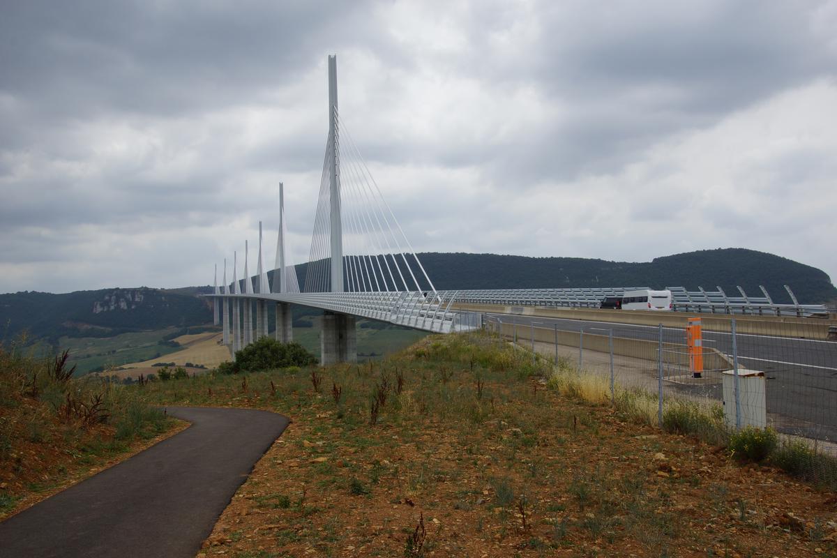
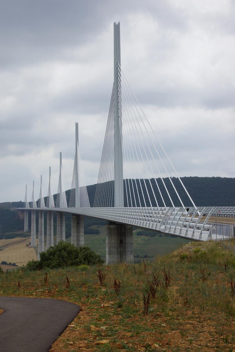
Fertige Brücke
Die Millau Brücke ist ein bedeutendes Beispiel für eine Reihung von Schrägkabelbrücken. In einer beeindruckenden Landschaft ist ein Bauwerk von großer Eleganz entstanden, das das Tal in großer Höhe mit Leichtigkeit überquert.
Auszug aus: Svensson, Holger; Schrägkabelbrücken (1. Ausgabe),Wilhelm Ernst & Sohn Verlag für Architektur und technische Wissenschaften GmbH, Berlin (Deutschland), ISBN 3433029776, 2011; S. 413-419
Participants
-
Sétra
- Michel Virlogeux (Entwurf)
- EEG Europe Etudes Gecti
- Société d'études R. Foucault et Associés
- SOGELERG
-
Foster and Partners
- Norman Foster (Architekt)
- Jean Piccardi (Stahl)
- François Schlosser (Geotechnik)
- Jean-Claude Foucriat (Stahl)
- ARCADIS
- Bureau d'études Greisch
- EEG Simecsol (Pfeiler)
- Société d'études R. Foucault et Associés
- STOA Eiffage
- Thales Engineering & Consulting
- Bureau d'études Greisch (Fahrbahntafel)

- Carl Stahl ARC GmbH (Geländer)


Relevant Web Sites
-
archINFORM: Millau-Viadukt


-
Aurelle-Verlac: Viaduc de Millau
-
BBC News: France 'completes' tallest bridge (29.05.2004)
-
Bernd Nebel: Brücken: Brücken in Europa: Viaduc de Millau
-
Broer.no: Millau Viaduct
-
Broer.no: Millau Viadukt

-
Christian Tardieu: Viaduc de Millau
-
HighestBridges.com: Millau Viaduct
-
Le Monde: web: conférence UTLS: le viaduc de Millau par M. Virlogeux
-
Météo France: Le Viaduc de Millau - Une assistance météo hors normes
-
OTUA: Ponts et ouvrages d'art: Le viaduc de Millau: l'acier de tous les exploits
-
OTUA: Viaduc de Millau
-
Planète TP: Viaduc de Millau
-
Viaduc de Millau
-
Wikipedia: Viaduc de Millau
Relevant Publications
- 28 poids lourds mettent le viaduc à l'épreuve. In: Le Moniteur des Travaux Publics et du Bâtiment, n. 5270 (26 November 2004), pp. 7.
- (2003): 36 000 t d'acier assemblées sur les rives du Tarn. In: Le Moniteur des Travaux Publics et du Bâtiment, n. 5210 (3 October 2003), pp. 99.
- (1997): A75. Puits de reconnaissance du Grand viaduc de Millau. Un ouvrage exceptionnel, reconnaissance géotechnique exceptionnelle. In: Travaux, n. 731 (May 1997), pp. 18-23.
- (2012): Ambient and free vibration tests of the Millau Viaduct: Evaluation of alternative processing strategies. In: Engineering Structures, v. 45 (December 2012), pp. 372-384.
- L'apogée du système Freyssinet. In: Sols et Structures, n. 220 ( 2004), pp. 6-11.
- About this
data sheet - Structure-ID
20000351 - Published on:
02/09/1999 - Last updated on:
01/03/2022


