First earthquake-proof railroad bridge expansion joint
The new intercity line Toluca–Mexico City is scheduled to become operational early in 2021. It has a length of 57.7 km. The daily passenger estimate is about 230,000 to 300,000. The investment volume amounts to 2.5 bn US$. Special feature is the seismic protection system for two long viaducts. For this purpose, so-called guided cross-ties, the first absolutely earthquake-proof railroad bridge expansion joints, are installed at the ends of the individual bridge sections.
Together with a complex system consisting of bearings, dampers and elastomeric spring isolators the bridge expansion joints ensure structural stability, function and safety for various load cases: from braking and acceleration forces in normal operation to the Maximum Considered Earthquake (MCE).
Region with extremely high seismic accelerations
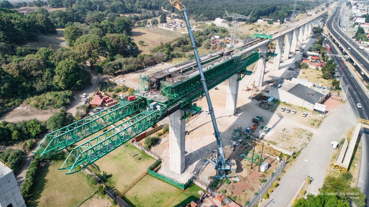
The frame conditions present a challenge. The two largest bridges, viaduct 2 (3,865 m long) and viaduct 4 (1,448 m), are situated in the mountains. Moreover, the region is highly earthquake-prone. The piers feature distances of up to 64 m and a height of up to 65 m. It is the first Mexican railroad project that includes viaducts of such dimensions in a region with extremely high seismic accelerations of up to 0.77 g. In view of these seismic forces, customary reinforcements by concrete and steel in the structure would have been neither sufficiently safe nor economically reasonable.
Combination of structural protection systems
Instead, a combination of different structural protection systems was used that allow for controlled movements and completely accommodate them, thus alleviating the seismic impacts. The very individual adjustment of the single structures to the influencing variables from an earthquake could only be realized in close cooperation between MAURER and the building planners. It is required that trains can safely cross the viaducts even immediately after a severe earthquake.
The following elements intertwine at the two large viaducts:
- The new, earthquake-proof guided cross-tie: this expansion joint installed at the individual ends of the bridge sections enables non-destructive thermal and seismic movements in all directions.
- Spherical bearings with the MSM® sliding material: the bearings between bridge deck and piers accommodate structural loads of 2,900 t and prevent lateral breakaway of the deck in case of a Design Basis Earthquake (DBE).
- Horizontally arranged hydraulic dampers: they block braking forces and limit the bridge displacement in longitudinal direction in case of an MCE (Maximum Considered Earthquake).
- Elastomeric spring isolators: they optimally re-center the bridge into neutral position in all seismic or service load cases.
- Concrete enclosures in transversal direction on each axis laterally at the bridge deck: they are activated in an emergency to prevent the bridge from collapsing.
Complexity as a challenge per se
The required force reductions in different load cases could only be achieved by deploying an individually adapted expansion joint, isolation and damper system with correspondingly designed freedom of movement or resilience, respectively. The particular challenge was to reconcile the different requirements in terms of permissible forces and simultaneous movements.
The maintenance-free protection system according to EN 15129 (seismic protection systems) significantly reduces the longitudinal forces acting on the bridge deck by factor 3-4. This allows for much smaller bearings and dampers. In this way, it was possible to realize the slim piers with relatively small foundation constructions as required by the architect. Along with significantly reduced total construction costs, the protection system guarantees high safety and functionality of the structure. Safety and functionality of the structure are definitely ensured even after a severe earthquake.
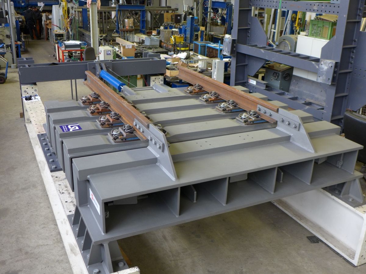
Earthquake-proof guided cross-tie
The key innovation was the guided cross-tie developed over years. It has been installed for the first time worldwide at the railroad line Toluca-Mexico City. With the help of the guided cross-tie, the tracks bridge the gap between the individual viaduct sections earthquake-proof. The guided cross-tie is based on the principle of the swivel joist expansion joint used in road constructions, although much more stable in order to withstand the high axle loads of crossing trains fatigue-free. The crucial safety advantage of the guided cross-tie: the movable bearings in the construction allow for “moving” or rotation of the cross-tie in and around the longitudinal, transversal and even the vertical axis.
Crossing trains do not cause considerable elastic deformations within the guided cross-tie. This enables train speeds of up to 350 km/h. The full seismic movements are compensated within the guided-cross tie without damages or plastic deformation, thus ensuring immediate crossing even after a severe earthquake.
For instance, at viaduct 2 one guided-cross tie per direction of travel was installed in five sections. In this way, each section can freely move thus drastically reducing the forces acting on the piers and the foundation. This leads to a higher load capacity and allows the design of the construction to be more economical by up to 10 %.
Spherical bearings for high pressure in the smallest of spaces
The viaducts feature individual span widths of 55 m to 64 m; the piers are up to 65 m tall and very slim. This is why two spherical bearings with high-molecular polyethylene material are provided per axis between deck and pier in order to reduce dimensions of the bearings by at least 40 % versus customary Teflon sliding bearings. Nonetheless, the challenge was that each bearing had to be designed with the smallest possible overall dimensions for a load of 2,900 t, a shear force of 5,100 kN, a movement of up to ±1.150 mm and a rotation of 2 %. The longitudinal movements of the deck proceed constraint-free with sliding friction of only 1-2 %. In case of an earthquake, the spherical bearings act as isolators and can freely move within a range of approx. ±450 mm.
The 142 spherical bearings have maximum dimensions of 3.2 x 1.2 x 0.32 m and weigh 4.5 t.
Hydraulic dampers for the braking forces
In the middle of each bridge section, up to six hydraulic dampers rest on a pier. They block the pulsed dynamic braking forces of the trains in the longitudinal direction of the bridge and prevent bridge deck displacements exceeding the permissible 10 mm. Hence, the crucial parameter for the damper design was the extremely fast response behavior at a deck movement of 1-2 mm/s along with the required power of resistance of 3,000 kN. The damper system allows for slow thermal deck movements without significant resistance.
Displacement limited in the MCE case
At the same time, these dampers limit the deck displacement to ±450 mm in case of an MCE. For this purpose, each damper has been designed with a response force of up to 3,000 kN, which means a total of 24,000 kN per section stabilize the deck.
To re-center the bridge sections during and after an earthquake, 52 elastomeric spring isolators were installed together with the hydraulic dampers. They act as elastic fixed points and bring the deck back into the central position. Due to the high requirements placed on the dampers and elastomeric spring isolators, they have been tested in two institutes: on the “shake table” of the University of California in San Diego and on the earthquake simulator of the University of Messina.
Lateral concrete guides as anti-collapse protection
One freely movable and one laterally guided spherical bearing rest on each axis. The guided bearing prevents a lateral breakaway of the tracks in the DBE case. At higher forces in MCE load cases, the bearing guide gives way and the constructive concrete enclosure acts as an additional safety system on the piers so that the bridge cannot collapse.
The last step scheduled is the installation of the guided cross-ties at viaduct 4 in the third quarter of 2020.
 MAURER SE