
General Information
| Other name(s): | Stöbnitztalbrücke |
|---|---|
| Completion: | 2013 |
| Status: | in use |
Project Type
| Structure: |
Double T-section girder bridge |
|---|---|
| Support conditions: |
for registered users |
| Function / usage: |
High-speed rail bridge |
| Material: |
Prestressed concrete bridge |
Awards and Distinctions
| 2015 |
entry
for registered users |
|---|
Location
| Location: |
Oechlitz, Mücheln (Geiseltal), Saalekreis, Saxony-Anhalt, Germany |
|---|---|
| Part of: | |
| Coordinates: | 51° 19' 53.67" N 11° 46' 12.94" E |
Technical Information
Dimensions
| length | 297 m | |
| span lengths | 22.00 m - 3 x 24.00 m - 6.50 m - 4 x 24.00 m - 6.50 m - 3 x 24.00 m - 22.00 m | |
| number of spans | 14 | |
| girder depth | 1.95 m |
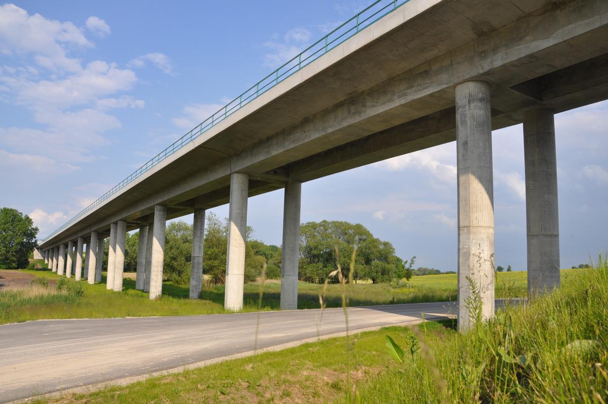
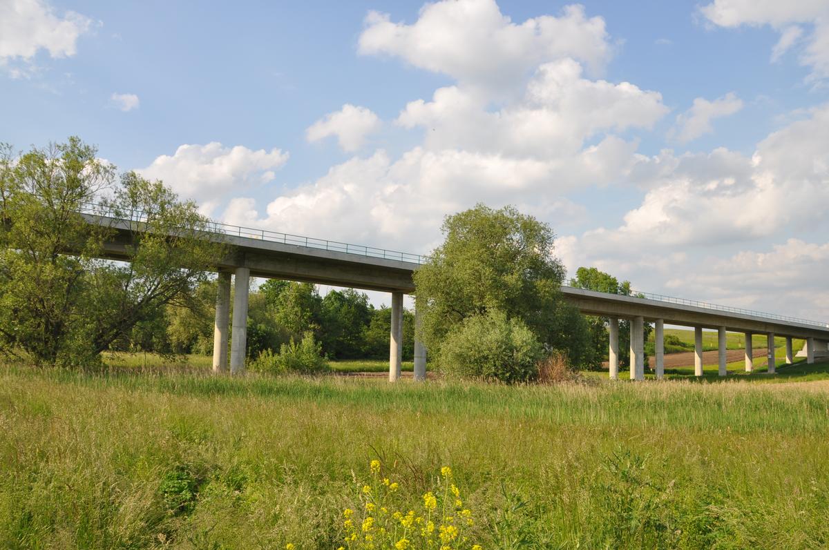
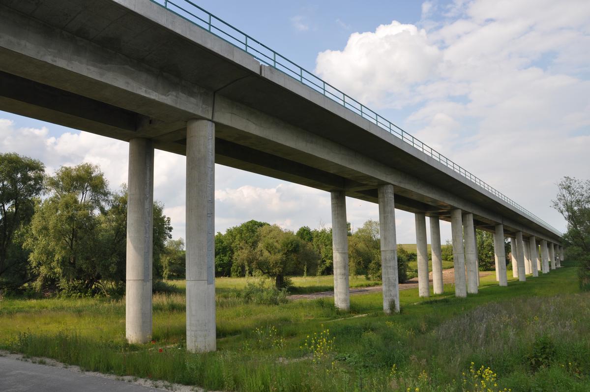
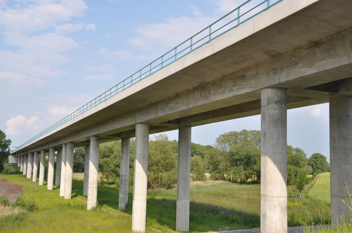
EÜ Stöbnitztal bridge in the course of the NBS Erfurt – Halle / Leipzig
Task of the contractor
In the course of the new railroad line between Erfurt and Leipzig/Halle, DB AG for the first time implemented novel structural designs deviating from the valid outline planning of viaducts. The aim was to improve the design of the structures while complying with the technical, economic and planning-law framework conditions and, at the same time, improving durability and reducing maintenance costs in accordance with the new guideline on the design of railroad bridges.
Nevertheless, in the case of the Stöbnitztal bridge, the invitation to tender and award of contract for a design based on the framework planning of DB AG valley bridges was carried out as a continuous girder with a flat plate girder as the superstructure cross-section in solid construction.
The design on which the tender was based was based on the framework planning for DB AG viaducts. To avoid rail pullouts, the bridge was divided into a continuous girder chain consisting of two 2-span continuous girders in the peripheral areas and two 5-span continuous girders in the central areas. The superstructures were to be supported on spherical bearings. To transfer the horizontal forces, the superstructures were supported on longitudinally fixed bearings at the abutments and at the double supports. Movable bearings were provided in all other axes. The superstructure was designed as a longitudinally prestressed plate girder. The column shafts had a circular cross-section. The double supports under the central continuous girders were to be connected by a reinforced concrete beam in the longitudinal direction of the bridge to form a frame, thus acting as brake blocks to absorb the horizontal forces. To accommodate the bearings and presses, capitelike pier heads were provided on the circular piers, which were costly to fabricate and unsatisfactory in terms of design. The box-shaped abutments were planned according to the framework planning of the viaducts as solid structures that cannot be walked on, with a bearing bench and a watertight transition joint between the chamber wall and the superstructure. Due to the subsoil situation is characterized by thick non-load-bearing layers over a good load-bearing claystone. A deep foundation on large-diameter drilled piles up to 25 m long was required.
Description of the construction
In the course of the recorded execution planning, a special proposal was developed as an integral railroad viaduct without bearings.
The basic idea of the alternative new design was the omission of the fixed bearings and the extensive omission of the remaining bearings and joints while maintaining the spans and pier positions as in the official design, since this was in accordance with the specifications of the plan approval. Since bearing and joint designs are not only more costly to manufacture but also incur higher costs for maintenance and upkeep in later use, it was possible to achieve holistic economic advantages compared with the original design.
The double supports planned for transferring the braking loads were monolithically connected to the superstructure. Thus, the original fixed point design to avoid rail pullouts could be easily implemented. As a positive side effect, it was possible to dispense with the roadway transitions at the abutments and to significantly reduce the end tangent angles in the edge spans. The reduction in superstructure torsion has additional positive effects for rail tension and ride comfort. The monolithic connection of the double supports to the superstructure also eliminated the need for stiffening walers between the circular supports. The elimination of the stiffening ledgers not only simplifies fabrication but also considerably improves the design. Bracing elements often have a disturbing effect on the harmonious rhythm of the piers and are incomprehensible to the observer.
Further, the longitudinally displaceable bearings of the piers adjacent to the fixed points were replaced by likewise monolithic connections. To reduce the constraining forces due to temperature expansion, creep and shrinkage, and braking and starting forces, the foundations under these piers were designed as a row of piles. This extends the span of the quasi double-restrained pier well into the piles. The thus determined restraint reinforcement between pier and superstructure could thus be produced without any problems.
Consequently, the bearings on the separating piers were also eliminated. Following the principle of horizontal stiffness reduction, the separation pier was „cut open“ in the middle. The two resulting semicircular cross sections are each monolithically connected to the superstructure. In terms of statics, the pier has the shape of a tuning fork.
In the view of the structure, the separating pier cannot be distinguished from the normal piers, which contributes to the design quality of the structure. The omission of the bearings as well as the pier capitals and bracing elements results in a comparatively simple and at the same time slender and transparent structure design for a railroad bridge.
Choice of construction materials
The superstructure is made of concrete C40/50 reinforced with BSt 500 S high-ductility reinforcing steel. It is prestressed in the longitudinal direction with prestressing steel St 1680/1880.
The substructures are made of concrete C20/25 to C35/45 reinforced with reinforcing steel BSt 500 S, depending on the load.
Special engineering performance
By reducing the structure to the slab beam superstructure and the circular columns, a very clear and simple design concept was successfully implemented. In doing so, all disturbing elements for bracing or for the installation and replacement of the bearings could be omitted. The result is a very transparent appearance for a railroad bridge.
Nevertheless, it was possible to dispense with rail extension devices, which requires high longitudinal stiffness and sectional division of the structure.
Due to the integral construction method, a „consent in individual cases“ (ZiE) was required on the part of the Federal Railway Authority (EBA) in the course of execution planning, since the previous range of experience for such railroad bridges was left. The basis for the ZiE was a prior application for „internal company approval“ (UIG) on the part of DB Netz AG.
Through extensive proofs, it could be shown that the alternative design reliably fulfills the requirements according to DIN technical reports 101 and 102 as well as guideline 804, and thus equivalence to conventional construction methods is given.
Explanatory report by Leonhardt, Andrä und Partner Beratende Ingenieure VBI AG for submission to the Ulrich Finsterwalder Ingenieurbaupreis 2015.
Participants
Owner
Client
Object planning
Alternative design
Structural engineering

Checking engineering
- Harald P. Hartmann (checking engineer)
Contractor
Construction supervision
Relevant Web Sites
There currently are no relevant websites listed.
Relevant Publications
- (2011): Entwurf und Ausführungsplanung der Stöbnitztalbrücke. Eine lagerlose Eisenbahnbrücke im Zuge der Neubaustrecke Erfurt – Leipzig/Halle. In: Beton- und Stahlbetonbau, v. 106, n. 2 (February 2011), pp. 81-88.
- About this
data sheet - Structure-ID
20020087 - Published on:
18/03/2006 - Last updated on:
05/02/2016
Structurae cooperates with


