
Shenzhen Bao'an International Airport Terminal 3
General Information
Project Type
| Structure: |
roof: Truss |
|---|---|
| Function / usage: |
Airport terminal building |
| Material: |
roof: Steel structure |
Awards and Distinctions
| 2015 |
entry
for registered users |
|---|
Location
| Location: |
Shenzhen, Guangdong, China |
|---|---|
| Address: | Bao'an |
| Coordinates: | 22° 37' 42.13" N 113° 48' 28.05" E |
Technical Information
Dimensions
| length | 1.6 km | |
| gross floor area | 450 000 m² |
Materials
| façade |
aluminum
|
|---|---|
| building structure |
steel
|
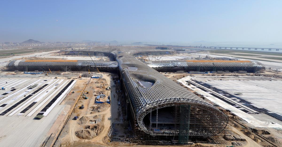
Shenzhen Bao'an International Airport Terminal 3 supporting structure and facade
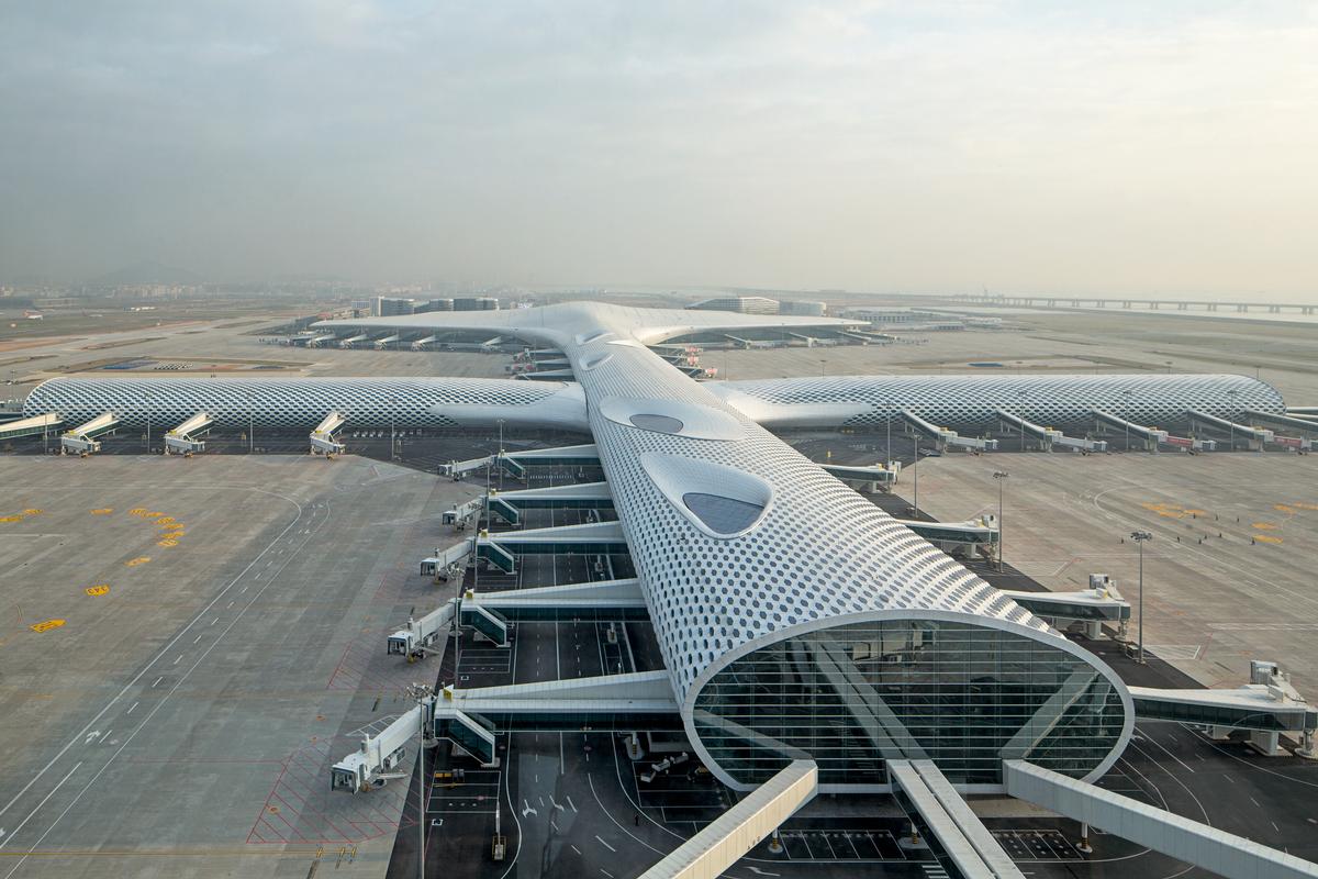
The new construction of Terminal 3 of Shenzhen Bao'an International Airport is based on the successful competition entry of architects Massimiliano and Doriana Fuksas, Rome supported by the Stuttgart engineering team of Jan Knippers and Thorsten Helbig from Stuttgart.
A free-form terminal shape was developed on a building organization and floor plan structure specified by the airport company, with a double-layered, perforated envelope structure that allows for differentiated controlled daylight penetration. The total area of the project is approx. 400,000m² and, including the connected traffic center, extends over a total length of approx. 1,500 meters. The new building of Terminal 3 with the dimensions L × W × H = 1251 × 642 × 43 meters completely replaces the existing airport and has a capacity of 24 million passengers per year. In further expansion stages, the capacity is to be increased to 45 million passengers by 2035.
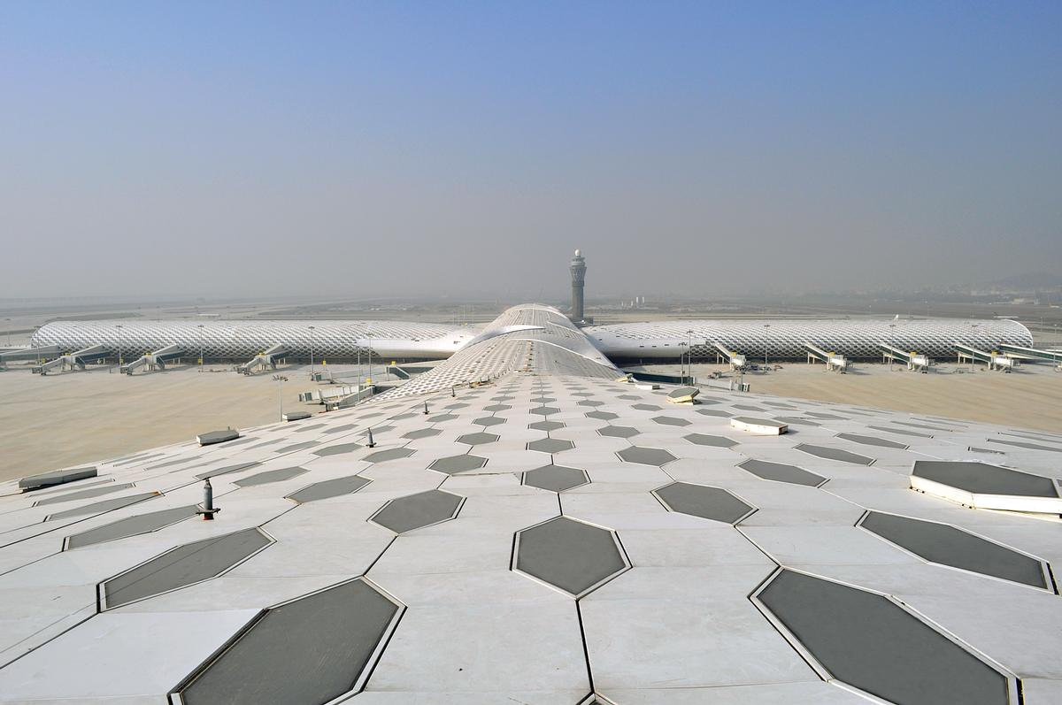
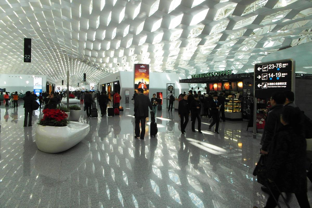
A striking feature of the free-form building structure is the perforated façade envelope, which specifically generates alternating daylight situations in the concourse. The nearly 300,000-square-meter, free-form envelope consists of two facade levels, each with approximately 25,000 hexagonal openings. During the competition, which was held between eight international teams of architects and engineers, the concept of a two-layer space frame made of hollow steel sections was developed, which reacts statically efficiently to the respective spans and geometric boundary conditions of the architecturally set form of the terminal hall and the concourses via the spacing of the chord layers. Thus, the slightly curved roof of the 642-meter-wide entrance hall is designed as a two-axis spanning truss grid with chord spacing of a maximum of 4.5 meters. The vertical loads in the orthogonally aligned system are transferred in two directions between supports spaced 36 meters apart. Like a table, the columns are flexurally rigidly integrated into the roof structure and are articulated to the floor level. The drainage system for the terminal roof, which covers an area of around 50,000 square meters, is also integrated into the supports, which taper conically towards the base.
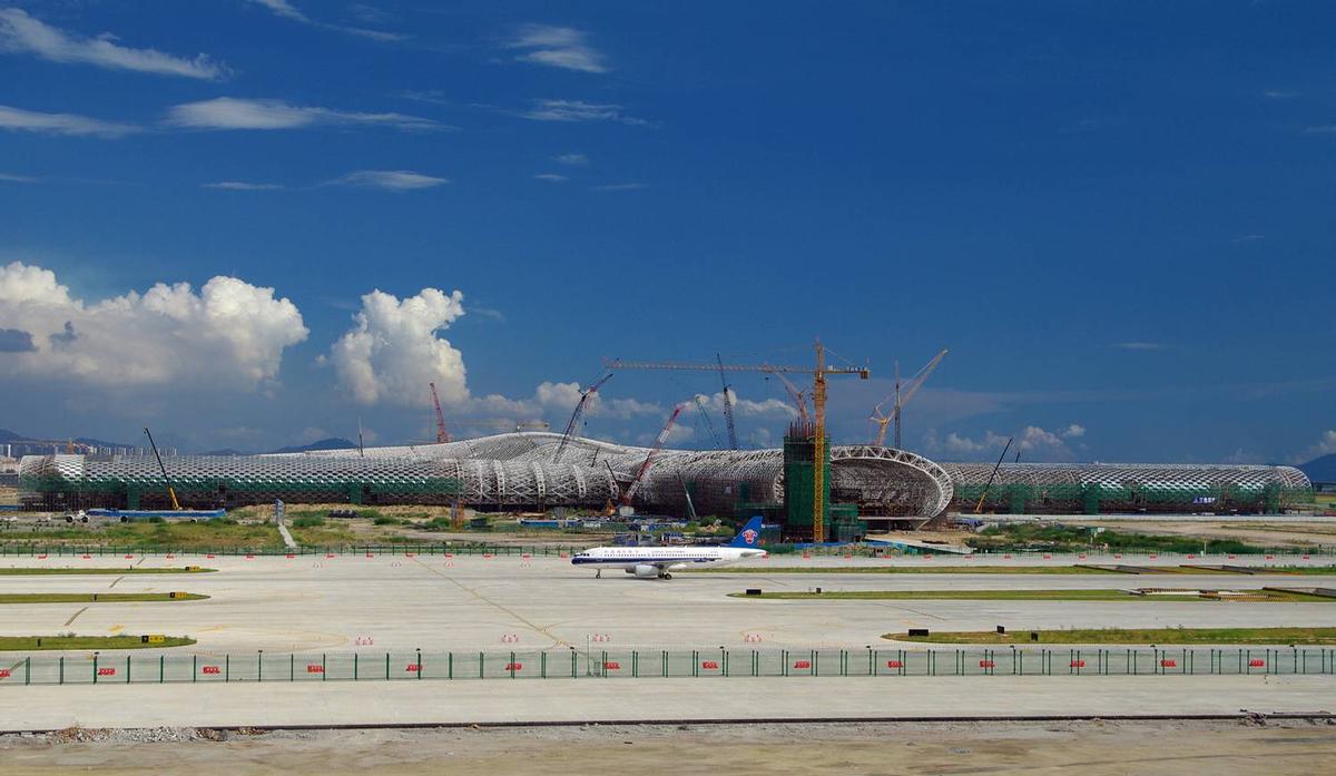
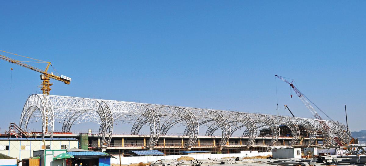
The arched roof structures of the 'main concourse' (length approx. 750 meters) and the 'cross concourses (total length approx. 600 meters) span 43 meters without supports and bulge out laterally up to 65 meters. At the intersection with the cross concourses, which branch off transversely at half their length, the hall widens out to form a piazza approximately 80 meters wide. In the intersection area, tree-like support structures support the arched girders. The horizontal support components are short-circuited by tension rods at the base level.
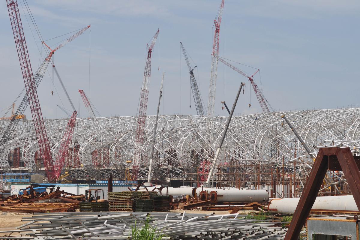
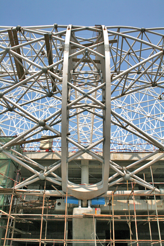
Numerous variations were investigated to develop an efficient support structure for the architecturally set hexagonal façade perforations that fit between the exterior and interior envelopes for the concourse. A diagonal alignment of the structure corresponding to the openings is not in itself a favorable solution because it does not follow the direct load path between the support lines. This function is taken over by the main arches arranged at intervals of 18 meters, which are designed as "twin girders". By dividing a wide single truss running centrally in the opening into two slender girder halves shifted into the edge areas of the hexagonal opening, the view through the windows is improved. The twin girders, arranged at regular intervals of 18 meters, consist of assembled rectangular hollow sections whose wall thicknesses are optimized with regard to local stresses. At the point of support, these are joined to form a large-format casting. Thanks to the high number of repetitions, the high cost of the casting molds can be spread over many parts and is therefore more economical than a solution composed of individual sheets and welded together. At the time of their manufacture, these were among the largest castings made in China up to that time.
On the part of the client and the 'expert commission' appointed by state authorities, high attention was paid not only to the feasibility of the proposed solutions in the context of Chinese standardization and construction practice, but also to the design weight of the conceived space truss solution. Based on experience with the enormously high steel consumption for the roof structures of the sports buildings for the Olympics, special constructions were suspected of being uneconomical a priori. In order to minimize material consumption, the chord layer spacings were largely adjusted in accordance with the local bending moment stresses in line with the architectural intentions. Further profile optimization was achieved through iterative cross-section grading in the parametric generation process.
The segmentation of the 1251-meter-long roof structure poses a particular structural engineering challenge. Compared to concrete structures, the steel structure exhibits greater temperature-induced changes in length. To minimize mutual constraints, a special support strategy was developed. Two opposing optimization strategies had to be reconciled: On the one hand, longitudinal expansion of the steel structure due to temperature expansion should be as unhindered as possible. For this purpose, a longitudinal, sliding support of the structure section starting from a central fixed point is most suitable. On the other hand, in the case of high horizontal accelerations in the longitudinal direction, as can occur during an earthquake, the resulting forces must be distributed over as many horizontal bearings as possible to avoid high local load peaks. 'Spring-loaded' bearings were therefore provided in the concourse longitudinal direction. The springs are set in such a way that the thermally induced longitudinal expansions are only resisted to a small extent, but in the case of strong horizontal acceleration due to earthquakes, an almost uniform distribution of the bearing forces is achieved. The differently calibrated, degressively adjusted spring characteristics required for this are realized with disc springs arranged on both sides of the bearing point.
However, in addition to the classic 'design process', in which we designed and implemented the structure and facade in close collaboration with the architect, from the structural concept to the development and execution of the bearing detail, the 'process design' was the key to the implementation of the relatively large and complex terminal project in only five and a half years from competition to completion.
The common, parametric-based data platform was developed by Knippers Helbig, refined during the design process and the initial data handed over for execution. The specially developed script places reference points of the panel elements on the freely shaped envelope surfaces developed by the architects at the specified center distance. Within the cell thus defined, a geometrically based algorithm then determines all other corner points of the system axes for the transparent and opaque panel segments. Between the reference points of the outer and inner enveloping surfaces, the programmed geometric references yield the intervening spatial structure. The script is thus able to develop the complete geometry of the system axes of the supporting structure with approximately 200,000 individual bars and the facade consisting of 60,000 elements based on specified envelope surface models.
Bao'an Airport is thus the largest construction project to date that has been developed and built on the basis of a parametric-based model. This approach opens up fundamentally new possibilities for the planning and construction of the future. Not only can geometrically complex structures and facades that were previously inconceivable be planned. In the parametrically organized overall model, static, building physics and energy aspects can be linked in such a way that the algorithm only allows solutions that lie within the targeted solution space of all considered characteristics. The design process is then no longer a successive processing of individual design-determining factors but a linking of the partial aspects in a simultaneous and multi-criteria optimization. The parametric-based design method holds the potential for a paradigm shift for the role of the engineer and all participants in the design process.
Engineers have it in their own hands whether they actively help develop, shape and fill in the 'process design' or leave the field to others.
Explanatory report by Knippers Helbig Advanced Engineering for submission to the Ulrich Finsterwalder Ingenieurbaupreis 2015
Author: Thorsten Helbig
Participants
Owner
Architecture
-
Massimiliano Fuksas architetto
- Massimiliano Fuksas (architect)
Structural engineering
Fire safety engineering

Relevant Web Sites

Relevant Publications
- (2014): Ein Luftfahrtterminal für das junge China - Shenzhen International Airport Terminal 3. In: (2014): Ingenieurbaukunst 2015. Ernst & Sohn, Berlin (Germany), ISBN 9783433030967, pp. 60-69.
- About this
data sheet - Structure-ID
20066223 - Published on:
29/05/2014 - Last updated on:
29/04/2021
Structurae cooperates with


