
General Information
| Completion: | 1978 |
|---|---|
| Status: | in use |
Project Type
| Function / usage: |
Hydroelectric dam / plant |
|---|
Awards and Distinctions
| 2015 |
commendation
for registered users |
|---|
Location
| Location: |
Iffezheim, Rastatt (Kreis), Baden-Württemberg, Germany |
|---|---|
| Impounds: |
|
| Coordinates: | 48° 49' 57.86" N 8° 6' 38.55" E |
Technical Information
Dimensions
| height difference | 11.0 m |
Quantities
| Extension | ||
|---|---|---|
| concrete volume | 55 000 m³ | |
| reinforcing steel | 5 500 t | |
| volume of earthworks | 85 500 m³ | |
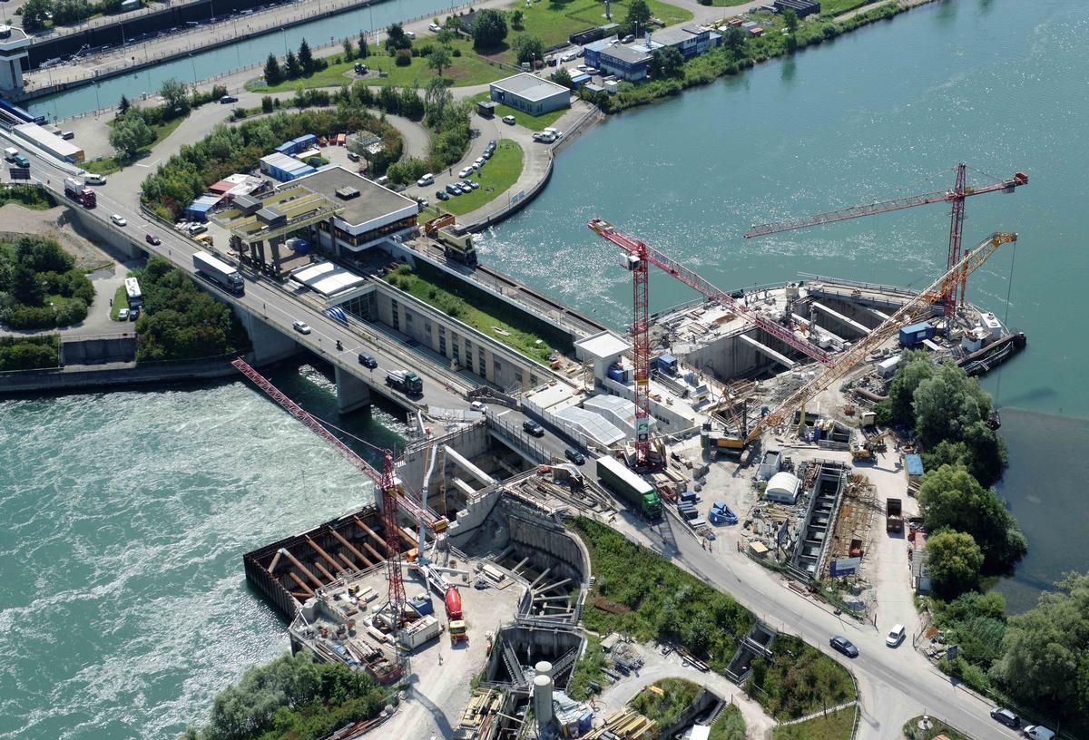
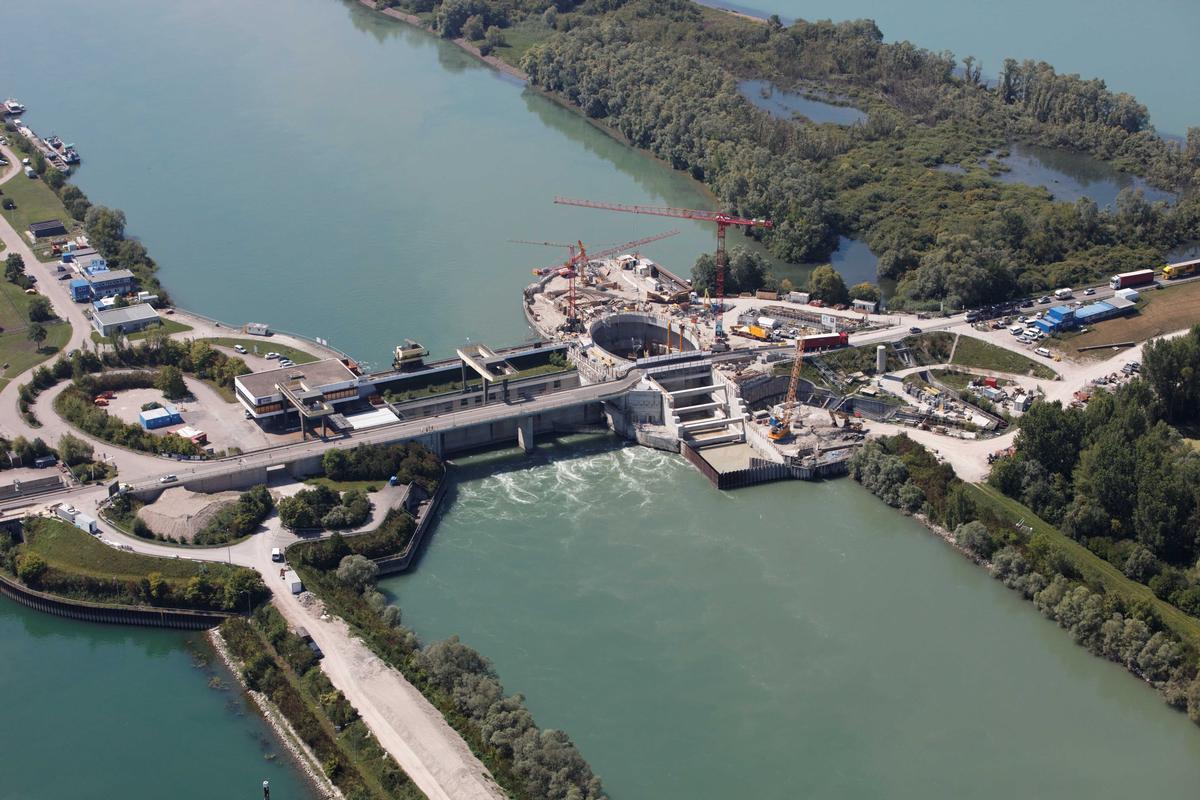
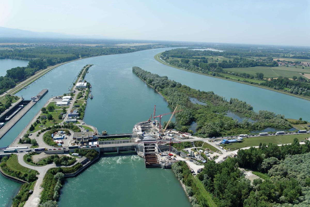
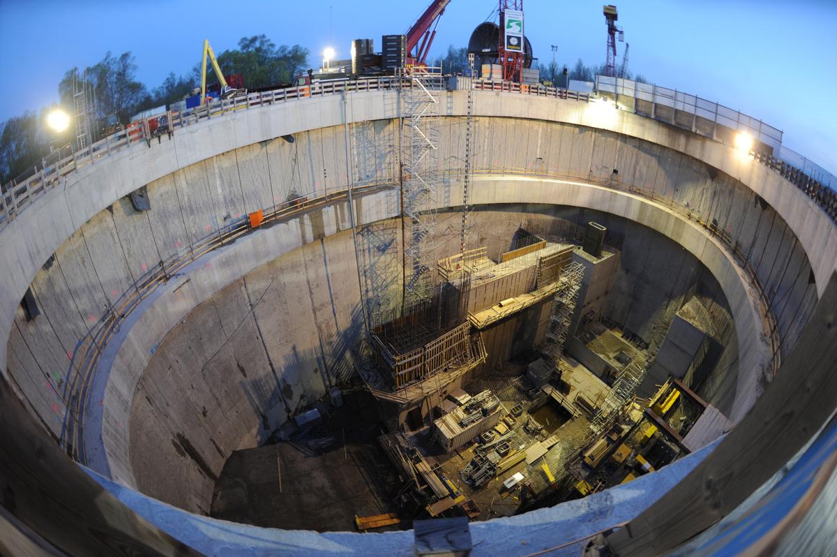
Construction pits for the extension of the Rhine power plant Iffezheim
1. Task definition
The Iffezheim barrage is located at Rhine-km 334.0 on the right side of the Rhine in an axis with a weir, a Rhine terminating dam and a lock. It is the tenth and last power plant in the Upper Rhine chain north of Basel. The existing power plant was commissioned in 1978. It is one of the largest run-of-river power plants in Europe and currently has four large bulb turbines. In the course of the expansion of the Rhine power plant Iffezheim, a joint power plant of EnBW Kraftwerke AG and EDF Electricité de France, with the installation of a fifth bulb turbine, the construction of three excavation pits is necessary, the headwater excavation pit (intake), the HBG (power plant) and the tailwater excavation pit (suction hose and outlet). All excavation pits are located within an island embankment adjacent to the existing power plant within the Rhine River. The construction area is crossed by the federal road B500 and a fish ladder, both of which had to be kept in operation during the entire construction work.
2. Description of the construction
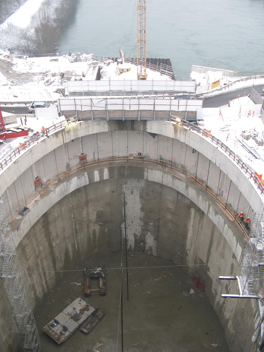
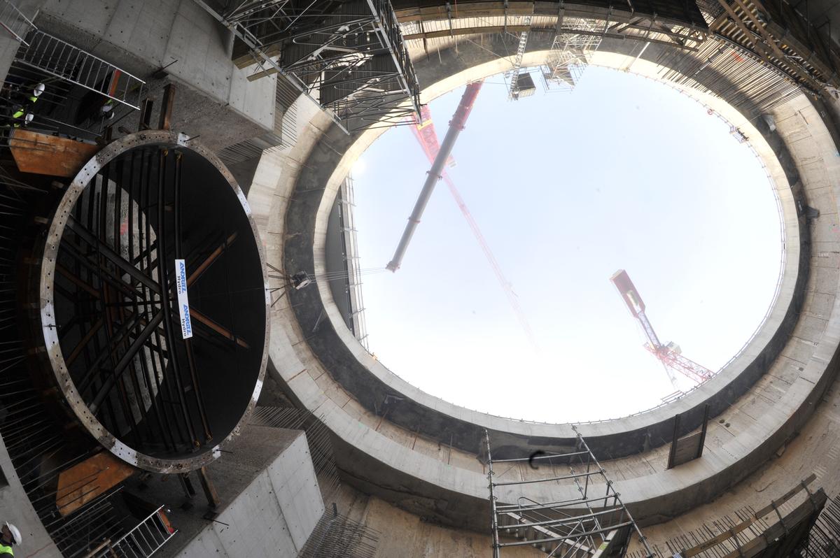
After extensive preliminary planning and conceptual studies by EnBW Kraftwerke AG and the design engineer RMD-Consult GmbH, the main construction pit with dimensions of 51 m by 36 m and an excavation depth of approx. 34 m was planned as an oval construction pit (basket-arched construction pit) with back-anchored underwater concrete base. A tie-back of the excavation pit walls is not possible, in particular due to the neighboring power plant buildings, stiffeners would have massively hindered the power plant construction.
The excavation pit wall consists of diaphragm walls (d = 1.50 m) produced by the grab method. To approximate the arch shape, the diaphragm wall was manufactured as a polygon with segment lengths of approx. 3.2 m. The diaphragm wall segments are separated from each other by formwork elements made of reinforced concrete (thickness 35 cm). The horizontal reinforcement is not continuous at the joints. In contrast to a continuous reinforcement, this allowed work processes to be saved during diaphragm wall construction and significantly accelerated production. After production of the diaphragm wall, a head beam was produced and, after a preliminary lift, a compression ring. The head beam is flexurally rigidly connected to the diaphragm wall slats. For the most part, only a transmission of compressive forces is possible between the thrust ring and diaphragm wall.
The lower end of the excavation pit was a 3 m thick underwater concrete base, which was anchored back against uplift with micropiles at a grid spacing of 2 m and a length of 35 m.
3. Choice of construction materials
- Slotted walls, head beams and thrust ring Reinforced concrete: C30/37, BSt 500
- Underwater concrete base: unreinforced C20/25
- Micropiles: Steel tension member GEWI 63.5 mm steel grade S 555/700
4. Special engineering work
Due to the shape of the main excavation pit and the asymmetrical load boundary conditions, as well as the mutual interaction of the excavation pits, among other things, when excavating the UW excavation pit with partially braced HBG (bedding reduction due to excavation of the UW excavation pit), a simplified analytical calculation or a calculation using structural models from structural engineering (e.g. with shell models) was not possible in the course of implementation planning. The basic prerequisite for the modeling was that, in addition to the structural components, the surrounding soil with element types and material laws was also included in a corresponding soil-mechanical three-dimensional FEM continuum model.
The HBG, the existing building ground, but also the existing neighboring buildings were taken into account. In particular, it was necessary to model the existing power plant closely adjoining the HBG in a westerly direction as well as the bank walls (gravity walls) located in the area of the HBG realistically in terms of their location and dimensions. Furthermore, the adjacent headwater and tailwater excavation pits had to be included in the model, since the excavation in the adjacent excavation pits had to be started due to the construction processes, while in the HBG partially stiffened conditions existed due to the installation of the power plant. In this respect, a mutual interaction between the individual excavation pits combined with a constant change in the bedding conditions of the excavation pit walls of the HBG during construction as well as partial deconstruction conditions during the installation of the power plant had to be recorded. The force flow from the HBG into the diaphragm walls of the UW excavation pit and the discharge there into the subsoil was also of essential importance.
When using correspondingly complex numerical calculation models for dimensioning structural components, it is necessary to check and verify the calculation model. This was done by plausibility considerations, especially with regard to the magnitude of the calculated earth pressures on the shoring walls. To further check and verify the calculation model, a large number of so-called sensitivity studies were carried out. Here, the various input parameters were varied in order to investigate their influence or the sensitivity of the overall model and to analyze the extent to which the internal forces required for the verifications of the component load-bearing capacity can be influenced, if necessary, by ground fluctuations, geometric imperfections or load positions.
Since soil-mechanical FEM program systems do not allow for an in-program reinforced concrete design with output of the required reinforcement ratios, the reinforced concrete design of the structural components was performed by transforming the internal forces obtained from the continuum model, taking into account the asymmetric boundary conditions. To verify the structural design, especially in the highly loaded transition areas from HBG to OW and UW excavation, an additional three-dimensional structural model was set up and calibrated against the soil mechanical continuum model calculation. Thereby, the comparison and calibration calculations in the structural model showed that derivations of a linear modulus of subgrade reaction based on the constrained modulus data in the subsoil report would not have been realistic.
Only through the special engineering effort using the three-dimensional soil mechanical continuum model was it possible to design the basket-arched (oval) excavation at all, taking into account the asymmetric actions and bedding conditions. Since a conventional, rectangular excavation was not feasible due to the geometric and, in particular, economic boundary conditions, it was only through this that the expansion of the Iffezheim Rhine power plant could be made possible.
Explanatory report by Kempfert + Partner Geotechnik for submission to the Ulrich Finsterwalder Ingenieurbaupreis 2015
Participants
Extension (2009-2014)
Owner
Design
Structural engineering
Co-contractor
Relevant Web Sites
There currently are no relevant websites listed.
Relevant Publications
- (2015): Elektro- und leittechnisches Konzept für den Zubau der 5. Turbine im Rheinkraftwerk Iffezheim. In: Wasserwirtschaft, v. 105, n. 1-2 (January 2015), pp. 70-75.
- (2015): Die elektro-mechanische Ausrüstung für den Zubau der 5. Turbine im Rheinkraftwerk Iffezheim. In: Wasserwirtschaft, v. 105, n. 1-2 (January 2015), pp. 59-64.
- (2015): Entwurfs- und Tragwerksplanung für die 5. Turbine im Rheinkraftwerk Iffezheim — 1. Planungsphase. In: Wasserwirtschaft, v. 105, n. 1-2 (January 2015), pp. 23-29.
- (2015): Entwurfs- und Tragwerksplanung für die 5. Turbine im Rheinkraftwerk Iffezheim — 2. Planungsphase. In: Wasserwirtschaft, v. 105, n. 1-2 (January 2015), pp. 30-35.
- (2015): Komplexer Baubehelf - Die Baugruben zur Erweiterung des Rheinkraftwerks Iffezheim. In: (2015): Ingenieurbaukunst 2016. Ernst & Sohn, Berlin (Germany), ISBN 9783433031261, pp. 76-83.
- About this
data sheet - Structure-ID
20066637 - Published on:
02/12/2014 - Last updated on:
21/04/2016
Structurae cooperates with


