
Steel Fibre Shotcrete in Tunnelling: State of the Art and Examples
There are many possibilities and reasons for the application of steel fibre concrete in tunnelling, which account for the manifold number of existing uses. The shotcreting construction method has been state of the art for many years, which is reflected in the following report.
Media
1 Introduction
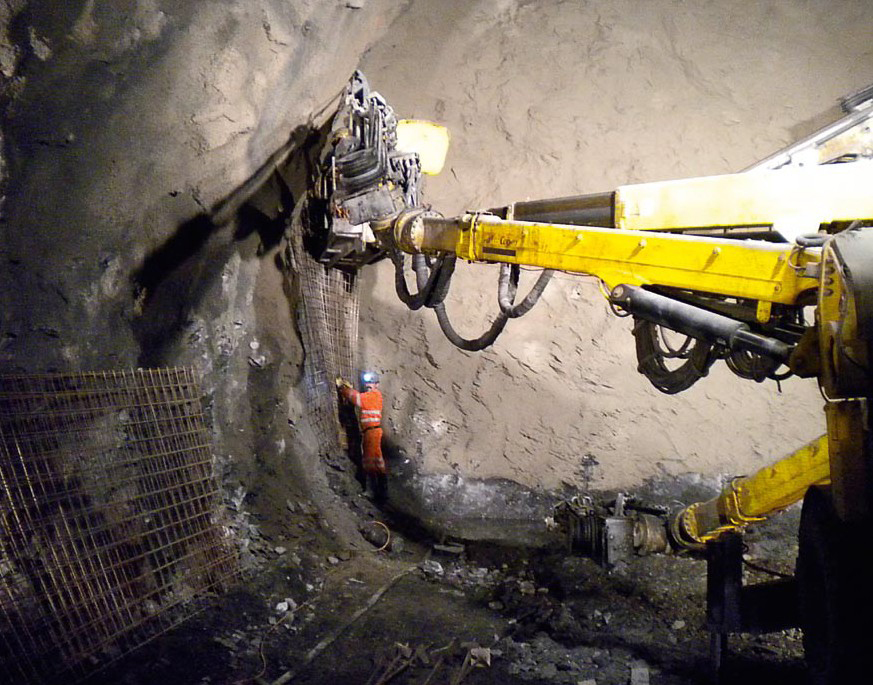
The readiness to apply steel fibre shotcrete in tunnelling increases with demands on safety, processtechnological streamlining and reducing the construction time, which facilitates the use of the material as well as costs, which are saved compared with a conventional reinforced concrete structural solution. With regard to the shotcreting method steel fibre concrete offers the advantage that there is no need for the extremely complicated and time-consuming installation of reinforcement (Fig. 1).
The construction process is speeded up. Furthermore the initial securing of the rock sets in at an early stage. Loosening of the rock occurs between driving the cross-section and activating the support given tricky geological conditions. In the case of poor rock conditions early activation of the bearing effect of the support helps achieve the target. This early bearing behaviour is attained by the speedy installation method and the early setting strength. The addition of the steel fibres in the shotcreting process generally takes place via dosing units for the ready mix in the concrete plant. In the case of steel fibre shotcrete the rebound, which leads to a slight fibre content in the tunnel shell compared with the ready mix, must be taken into consideration. Owing to the driving process orientation of the fibres perpendicular to the direction of placement is to be observed, something which can be assessed as positive regarding the bearing characteristics. In the case of steel fibre shotcrete the 2 previously mentioned effects lead to test specimens being produced and evaluated to establish the energy absorption capacity under the same conditions prevailing at the subsequent structure. The longer and thinner the steel fibres are the more positive their influence on the ductility, bearing capacity and energy absorption capacity of the steel fibre shotcrete is. However the fibre length should be restricted to some 35 mm on account of processibility and should not exceed 2/3rd of the hose diameter.
2 Material Properties of Steel Fibre Shotcrete
Steel wire fibres are mixed with concrete, in order to improve various mechanical properties of the concrete quite apart from enhancing the bearing effect. The decisive characteristics, which are considerably improved through the addition of steel wire fibres, include:
- increased ductility given tension and pressure
- enhanced impact strength
- improved fatigue behaviour
- low propensity for spalling
- increased durability
- slighter crack widths in operational state
- bending tensile capacity in all 3 spatial directions
Compared to applying conventional reinforced concrete the application of steel fibre concrete affords clear advantages in conjunction with the shotcreting method in tunnelling. In particular these relate to increased industrial safety, cost saving for the reinforcing operations as well as making the entire work cycle more straightforward and quicker. The sprayed layer is more homogeneous as no spraying shadows occur on account of spraying through reinforcement. In addition there is the fact that less overbreak has to be sprayed as the rock contours can be followed better.
3 Standardising Steel Fibres in the EN 14889-1
In Europe steel fibres for application in concrete have to be accorded the CE marking. The minimum requirements for steel fibres are described in the standardised norm EN 14889-1 [6]. The norm establishes requirements for concrete, mortar and grouting mortar for bearing and other purposes. There are 2 different systems for certificating the conformity:
- System 1 – steel fibres for bearing purposes and
- System 3 – steel fibres forother purposes.
The norm defines bearing purposes as follows: "when applying fibres for bearing purposes the added fibres contribute towards the bearing capacity of a concrete element". Accordingly a System "1" certification of the conformity is necessary for practically all relevant cases. Thus only steel fibres monitored and certificated in accordance with System "1" with the relevant EU certificate of conformity should be applied in order to avoid any confusion. The norm contains the permissible tolerances for the properties of the fibres applicable in each case. In order to present differences in the capabilities of the individual types of fibres in a clear manner the influence on the concrete's strength is tested on a reference concrete. The minimum amount of added steel fibre is defined, which is necessary to attain a residual bending tensile strength of 1.5 N/mm² given a crack opening width of 0.5 mm and of 1.0 N/mm² given a crack opening width of 3.5 mm in a test procedure in accordance with DIN EN 14651 [5].
4 European Norm for Shotcrete in the EN 14487-1
The European norm for shotcrete EN 14887-1 [2] defines the application of fibres and describes necessary test methods to determine the ductility and capabilities of various fibre concretes. Two different test methods are included in this norm: statically undefined slab tests to determine the energy absorption capacity (system bearing capacity) according to EN 14488-5 [4] and statically defined beam tests to determine the cross-section bearing capacity according to EN 14488-3 [3]. Thus the EN 144887-1 [2] refers to other European norms relating to test methods, which are taken up and explained in the following chapter.
| Deformation area | Strength class (min. value) in [MPa] | ||||
|
Deformation |
S1 | S2 | S3 | S4 | |
| D1 | 0,5 to 1 | 1 | 2 | 3 | 4 |
| D2 | 0,5 to 2 | ||||
| D3 | 0,5 to 4 | ||||
Table 1: Definition of the residual Strength Classes
The classification of strength classes and relevant deflection according to EN 14488-3 [3] takes place in keeping with Table 1. It is important to observe that the selected strength value (S1-S4) does not undershoot the load-deformation curve at any point of the corresponding deformation area (D1-D3). The EN 14488-5 [4] defines the classes contained in Table 2 for the energy absorption capacity.
| Energy absorption class | Absorbed energy in joules given a deflection of max. 25 mm |
| E500 | 500 |
| E700 | 700 |
| E1000 | 1000 |
Table 2: Definition of the Energy Absorption Classes
Should the result of statically undefined slab tests permit a conclusion relating to the system bearing capacity (appropriately determined from typical backanchored shotcrete shells) to be reached, the outcome of beam tests enables the cross-sectional bearing capacity to be determined (appropriately applied in a calculation, in which the crosssectional bearing capacity is taken as material resistance). In this respect both the test methods as well as the results they produce differ. As a consequence results from slab tests cannot be applied for dimensioning, if the cross-sectional bearing capacity is included on the resistance side (usual procedure for bearing structure dimensioning).
5 Test Methods for Determining the Capability
5.1 Slab Test after EN 14488-5
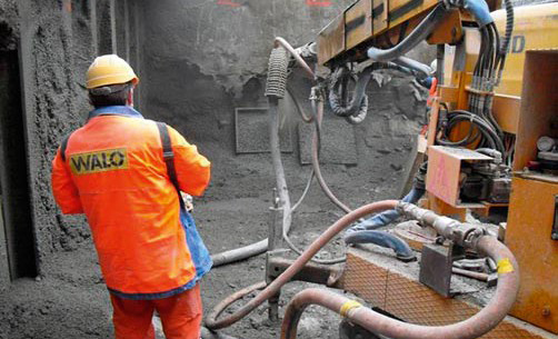
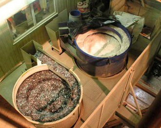
Determining the energy absorption for fibre-reinforced slabshapedtest specimens: the deformation-controlled test method takes a quadratic test specimen with the dimensions 600 x 600 mm and a slab thickness of 100 mm into account (please also see Fig. 12). This is produced under site conditions in order to take the effects of fibre orientation and fibre rebound into consideration (Fig. 2). The test specimen is set up so that it can rotate freely for the test and deformation- controlled via an individual load at the slab centre and a load applied up to a maximum deflection of 30 mm (evaluation takes place at 25 mm). The loaddeformation curve is recorded continuously. Subsequently the results are displayed in a diagram of the absorbed energy as a function of the deflection.
5.2 Statically defined Bending Beam Tests after EN 14488-3
Determining the bending strengths for fibre-reinforced slab-shaped test specimens: the deformation-controlled test method relates to a notched beam 500 mm in length, 125 mm wide and 75 mm high, which is cut from a previously sprayed quadratic slab. The test specimen is set on 2 freely rotating rollers for the test and deformation-controlled via 2 individual loads, each at the third points on the span width, and a load applied up to a maximum deflection of 40 mm. The loaddeformation curve is recorded continuously.
6 Long-term Behaviour of Fibre Concretes
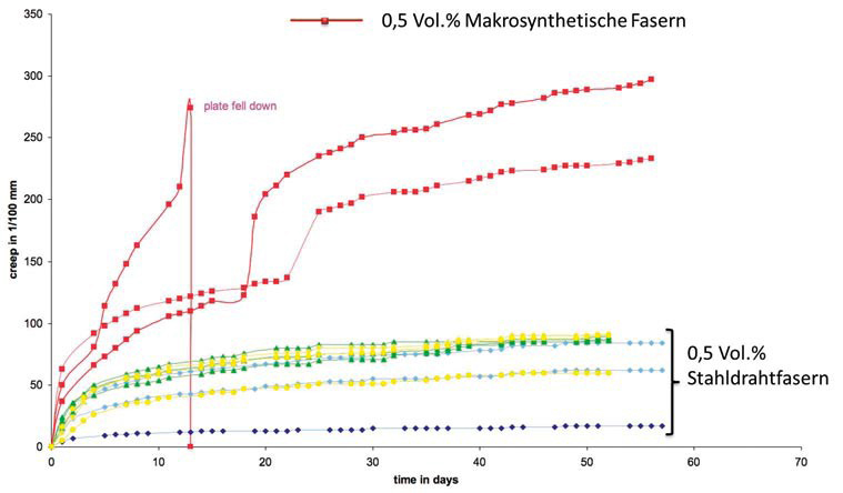
It is essential to observe the longterm behaviour of fibre concretes also when shotcrete is applied. Various creep tests have shown that the application of steel fibre concrete neither leads to substantial creep deformations nor to creep failure. On the other hand substantial creep deformations can be expected from plastic fibre concretes. Different publications describe this behaviour. For example a reference is made to the Austrian Guideline on "Fibre Concrete" [10], whose appendix contains results of creep tests. Most creep tests were executed on the basis of beam-shaped test specimens.
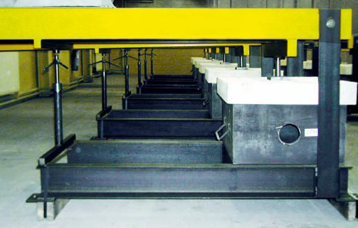
Investigations of the longterm behaviour on slab-shaped test specimens with dimensions in keeping with EN 14488-5 [4] led to similar results regarding the tendency of plastic fibre concretes to creep (Fig. 3). The load level for the long-term tests was set at only 60 % of the acceptable load derived from the shortterm tests and notwithstanding the inclination of the plastic fibre concretes to creep was observed after a relatively short time with varied real temperature differences (Fig. 4).
7 Reference Projects
Numerous tunnel projects have been accomplished in the course of recent years using steel fibre shotcrete. Three reference projects are now presented.
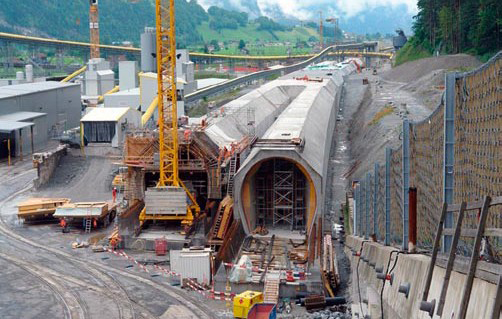
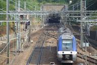
7.1 Gotthard Base Tunnel
The world's longest railway tunnel is being created in the shape of the 57 km long Gotthard Base Tunnel. It represents the core of a flat trajectory railway through the Alps. Bekaert (Schweiz) AG took up the project planning at a relatively early point in time – October 2001 – leading to a successful shotcrete concept with Dramix®, steel wire fibres and Duomix® PP. The entire tunnel route was split up into 5 sections with 3 intermediate points of attack (Amsteg, Sedrun and Faido) in order to reduce the construction time.The application of steel fibre shotcrete was concentrated on the sections where drill+blast drives were planned. Here it was possible to apply steel fibre shotcrete effectively for the rock supporting activities.
Erstfeld: Strabag (Schweiz) AG
The tunnel's north portal is located here. Apart from the outside facilities the 7.6 km long part-section (Herrenknecht TBMdrive) comprises 2 parallel singletrack tunnel bores. The first 600 m was tackled by cut-and-cover. The cut-and-cover tunnel with a volume of 40,000 m³ fire protection concrete is reinforced with Duomix M6, which was added through applying Incite MD400. The tunnelling contractor Strabag (Schweiz) AG also undertook the branching structures for further development "Gotthard lang" by drill+blast. Dramix RC- 65/35-BN was used for the steel fibre shotcrete mix (Fig. 5).
Amsteg: Strabag (Schweiz) AG
The 2 km long access tunnel was tackled via drill+blast, the rock secured by Dramix RC-65/25-BN. The Herrenknecht TBM drive for the 2 tunnel bores is executed some 12 km towards the south until the Sedrun part-section boundary from the Amsteg bottom point.
Sedrun: Transco Sedrun JV (Implenia CH, Frutiger CH, Bilfinger Berger D, Pizzarotti I)
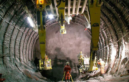
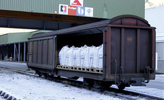
The geologically tricky zones towards the north and south (total length 6.2 km and a 3 km long extension of the section) were driven from the Sedrun intermediate point of attack via drill+blast (Fig. 6). Prior to the signing of the contract for supplying the steel fibres the responsible contractor Transco Sedrun JV checked the capabilities and production facilities (secure delivery). The demand to supply the steel fibres by rail to the site was successfully accomplished (Fig. 7). Collaboration between the JV, Holcim (Schweiz) AG and Bekaert (Schweiz) AG made it possible to transload the steel fibres in the Holcim Untervaz's cement plant on to the narrow-gauge track of the RhB (Rhaetian Railway). In each case transportation took place together with the cement train to Sedrun arriving at the main installation yard. For the Sedrun section alone more than 1,000 t of steel wire fibres glued fibre types, delivered in big bags of 1,100 kg, CE Label, System 1)were processed for steel fibre shotcrete per year. The entire concrete and steel fibre shotcrete production was undertaken by the Transco JV in the Doubrava concrete plant with 2 dosing units DE Incite SF 500 (1 unit Dramix® steel fibres, 1 Duomix ® M6 PP fibres) (Fig. 6). For the steel fibre shotcretes used for drill+blast activities among other things the demand for a recipe absolutely free of clumps was called for and successful achieved. Towards this end the Dramix® glued steel fibre types that were used proved their worth. The decision to supply the steel fibres in 1,100 km big bags and apply the automatic dosing system over the protracted construction period turned out to be the right one. In this manner the huge volumes required for initial supporting operations and securing the face were tackled safety and as scheduled (Table 3).
| Length of entire tunnel and gallery system | 151.80 | [km] |
| Excavation drill+blast | 66.30 (43,7) | [km (%)] |
| Lengths of advance | 0.8 bis 4.0 | [m] |
| Peak rate | 11.5 | [m/working day] |
| Average rate in favourable geology | 3.0 bis 4.5 | [m/working day] |
| Average rate unfavourable geology | 1.0 | [m/working day] |
| TBM drive (Herrenknecht) | ||
| TBM excavation | 85.5 (56.3) | [km (%)] |
| Average Erstfeld | 14 | [m/working day] |
| Peak rate Erstfeld | 56.0 | [m/working day] |
| TBM weight Erstfeld | 3000 | [t] |
| Material management | ||
| Total amount of excavated material | 25 | [Mio. t] |
| Concrete | 2.3 | [Mio. m³] |
| Bekaert steel fibres | 8.800 | [t] |
| Bekaert Duomix M6 | 105 | [t] |
Table 3: Project Key Figures for Roughwork – Gotthard Base Tunnel
(source: Medienstelle Alp Transit, 7.9.09)
Faido: TAT JV (Implenia CH, Alpine A, CSC Impresa SA I, Hochtief D, Impregilo)
The Faido southern intermediate point of attack embraces a 2.7 km long inclined tunnel with roughly 12 % gradient devised to reach the level of the future tunnel bores. The second Multi Function Station is also located here (Fig. 9). From this point the 2 main tunnel bores were driven with a Herrenknecht TBM 15 km towards Sedrun in the north. Dramix ® steel fibres were applied for the rock securing operations in the access tunnel and the Multi Function Station. Holcim,/Sika undertook the production of the steel fibre shotcrete.
Bodio: TAT JV (Implenia CH, Alpine A, CSC Impresa SA I, Hochtief S, Impregilo)
A section of soft ground was detoured with a by-pass tunnel in order to enable the underground assembly chamber for the Herrenknecht TBM to be set up more speedily. For the base of the bypass tunnel and the supporting shotcrete with Dramix® steel fibres and Duomix® M6 PP fibres were applied. 13 km was driven with the Herrenknecht TBM from Bodio.
7.2 Eyholz Tunnel
The Visp bypass represents a roughly 8 km long part-section of the A9 national highway in the Canton of Valais. Visp is bypassed in the south by 2 altogether roughly 7.5 km long tunnels Visp and Eyholz. Both tunnels each possess 2 bores, the A9 in the Visper Valley runs over the Staldbach bridge built between 2004 and 2006. To produce the links from and into the Vispertal a total of 5 underground forks, an access and exit tunnel in the Eyholz Tunnel as well as a refurbished section tunnel in the Visp Tunnel must be produced.
The Eyholz Tunnel forms the eastern part of the Visp bypass and consists of a north and south bore each 4.2 km in length (Fig. 10) The Hauptunnel Eyholz AG JV headed by the Frutiger AG Tunnelbau Thun is responsible for working out the project. The entire project is being tackled via drill+blast. The breakthrough is foreseen for early 2012.
The geological conditions in both tunnels are by and large well explored. In the Eyholz Tunnel an exploratory heading was produced in advance along the tunnel axis. On the Eyholz Tunnel's east side a rockslide as well as debris located above it must be penetrated. After some 500 m and a looping transition to the soft ground the 2 tunnel bores are located completely in rock. In the Eyholz Tunnel's Staldbach area the geological conditions were investigated with numerous exploratory drillholes in order to determine the soft ground overdeepening and a zone with unfavourable rock properties (graphite zone) with sufficient accuracy in order to ensure that the drives were properly geared to this.
The Visp bypass constitutes the execution of a major project, which involves a large number of different and sophisticated engineering and entrepreneurial tasks relating to driving the tunnel. As of September 15, 2011 the drive had progressed to 2,446 m in the north bore and 2,680 m in the south one. The total concrete and shotcrete production is carried out at the concrete plant set up on the main installation yard by the Eyholz JV. A transport and dosing system (Incite SF 500) was installed at the concrete plant for the economic and safe production of steel fibre shotcrete (Fig. 11). The delivery of steel wire fibre GH 65/35 (CE Label, System 1, glued steel fibre type) is carried out in big bags of 1,100 kg. The requirements posed on the steel ibre shotcrete were worked out by the Eyholz JV with all those involved on the basis of advance tests. The working capacity of the steel wire fibre dosage that was worked out was tested on the basis of slab tests at the Geo- Bau Labor, Chur/CH. An energy absorption capacity of 800 joules was attained thus exceeding the demanded value of 700 joules (Fig. 12). The application of steel fibre shotcrete as a safety element for securing the rock and in certain supporting profiles as a substitute for mat reinforcement confirmed itself as an efficient, safe and economic solution in the course of the ongoing project.
7.3 Violay Tunnel
The Viola Tunnel represents a roughly 3.9 km long part-section of the A 89, connecting Lyon and Bordeaux. The Violay Tunnel crosses the geographical line separating the Rhone and the Loire and runs over a practically straight alignment almost parallel to the western axis (Cote Loire) – Est Cote Rhone. The tunnel consists of 2 bores for traffic (Fig. 13). The geological conditions indicate rather ancient material with xtremely different deformation characteristics and in part, rock properties. For this reason it was decided to execute the partsection conventionally with a planned drill+blast operation. One of the main targets was to undertake initial supporting with steel fibre shotcrete. Within the scope of the project extensive advance tests were carried out, which deserve particular mention in connection with this scheme. Requirements on the energy absorption capacity were defined for the Violay Tunnel project after ENN 14488-5 [4] with a minimum value of 700 joules. The proposal to undertake this with 25 kg/m³ of Dramix® RC-65/35-BN was accepted. Three sample specimens were completed on site and following 28 days tested in the"Sigma Beton Laboratory"and correspondingly evaluated. On the basis of the following results that are listed it is evident that each individual slab lies under the required energy absorption capacity of 700 joules (Table 4 + 5) (Figs. 14 + 15).
| Deformation / load |
Slab 1 [KN] | Slab 2 [KN] | Slab 3 [KN] |
| Max. value [mm] | 55 | 56,4 | 56,6 |
| 5 | 54,6 | 42,6 | 48,5 |
| 15 | 39,1 | 34,9 | 26,4 |
| 25 | 23,6 | 22,7 | 15,5 |
Table 4: Evaluation of the individual Sample Slabs
| Deformation / energy absorption |
Slab 1 [joules] | Slab 2 [joules] | Slab 3 [joules] |
| Max. value [mm] | 1084,1 | 996,2 | 828,7 |
| 5 | 207,2 | 157,2 | 186 |
| 15 | 687,3 | 611,1 | 561,8 |
| 25 | 980,8 | 889,7 | 753,9 |
Table 5: Correlation to the energy absorption capacity for the individual Sample Slabs
Additional tests to determine the cross-section bearing capacity were executed in order to provide the structural planners with computational proof in the form of characteristic values for the component resistance. In contrast to the specifications of the EN 14488-3, 2-sided rectangular beams were produced instead of statically defined beams thus resulting in statically defined test specimens. The rectangular slabs were produced in keeping with EFNARC recommendation [7] and provide a number of advantages as opposed to the beams according to EN 14488-3 (Fig. 16):
- The same geometry as the slabs to determine the energy absorption capacity
- Greater tensile zone and in turn more homogeneous fibre distribution and lower variation
- No cutting out test specimens from a previously produced slab.
Fig. 17 displays the load-deformation diagrams resulting from the test set-up. Plastic fibre concretes were included in the test programme as well but independently. However it was decided to plump for the steel fibre concrete. The application of steel fibre shotcrete for securing the rock and in certain supporting profiles as a substitute for mat reinforcement proved to be the most efficient solution for this project.
References
- Bemessung von Stahlfaserbeton im Tunnelbau, B.Maidl, A.Nitschke, M. Ortu, Bochum, Juni 1999
- EN 14487-1, Spritzbeton – Teil1: Begriffe, Festlegungen und Konformität
- EN 14488-3, Prüfung von Spritzbeton – Teil 3: Biegefestigkeiten (Erstriss-, Biegezug- und Restfestigkeit) faserverstärkter balkenförmiger Betonprüfkörper
- EN 14488-5, Prüfung von Spritzbeton – Teil 5: Bestimmung der Energieabsorption bei faserverstärkten plattenförmigen Prüfkörpern
- EN 14651, Prüfverfahren für Beton mit metallischen Fasern – Bestimmung der Biegezugfestigkeit (Proportionalitätsgrenze, residuelle Biegezugfestigkeit)
- EN 14889-1, Fasern für den Beton – Teil 1, Stahlfasern – Begriffe, Festlegungen und Konformität
- EFNARC, Three point bending test on a square panel with notch, Flexural tensile strength of fibre concrete on sprayed test specimen, June 2011
- Model Code 2010, First complete draft, Volume 1, bulletin 55
- Österreichische Vereinigung für Beton- und Bautechnik "Richtlinie Faserbeton" Fassung Juli 2008
- SIA 162/6: 1999 Empfehlung Stahlfaserbeton
- De Rivaz Benoit, Violay Tunnel- Steel fibre reinforced spray concrete for compliance with site safety requirement
- D. Hansel, P.Guirguis, Stahlfaserbetontübbinge: Stand der Technik und realisierte Projekte, Tunnel 1/2011
- Alex Schneider, Bruno Saller: Anspruchsvoller Tunnelbau in Lockergestein und Fels, Tunnelbau-Schweizer Bau Journal – SBJ 2/09
References


Structure Types


- About this
data sheet - Product-ID
7210 - Published on:
28/10/2014 - Last updated on:
01/03/2019