
New Lahntal Bridge with super-slim piers
The old Lahntal Bridge located in Limburg dates back to the early nineteen-sixties and is 400 m long. Every day about 100,000 vehicles crossed the valley of the River Lahn on the viaduct. The traffic load of one of the busiest motorway viaducts in Germany had increased sharply, so a new bridge had been built sited just a few metres west of the old viaduct. The new Lahntal viaduct measures a massive 43.50 m overall in width. It offers a total of eight lanes, plus hard shoulders. A major improvement compared to the old motorway bridge: It had only six lanes and no hard shoulder.
Media
Work started in September 2013 and the new bridge opened for traffic end of 2016. The project was funded by Germany's federal government and total costs will be around 92.7 million Euros. The old bridge is due to be fully demolished and removed by autumn 2017. Work overall is scheduled for completion by the end of 2017.
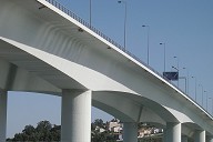
New bridge is 450 m long and 62 m high
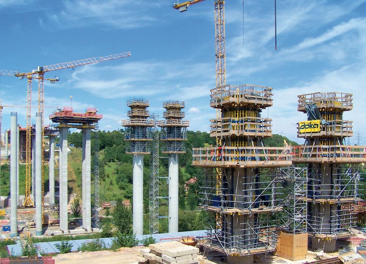
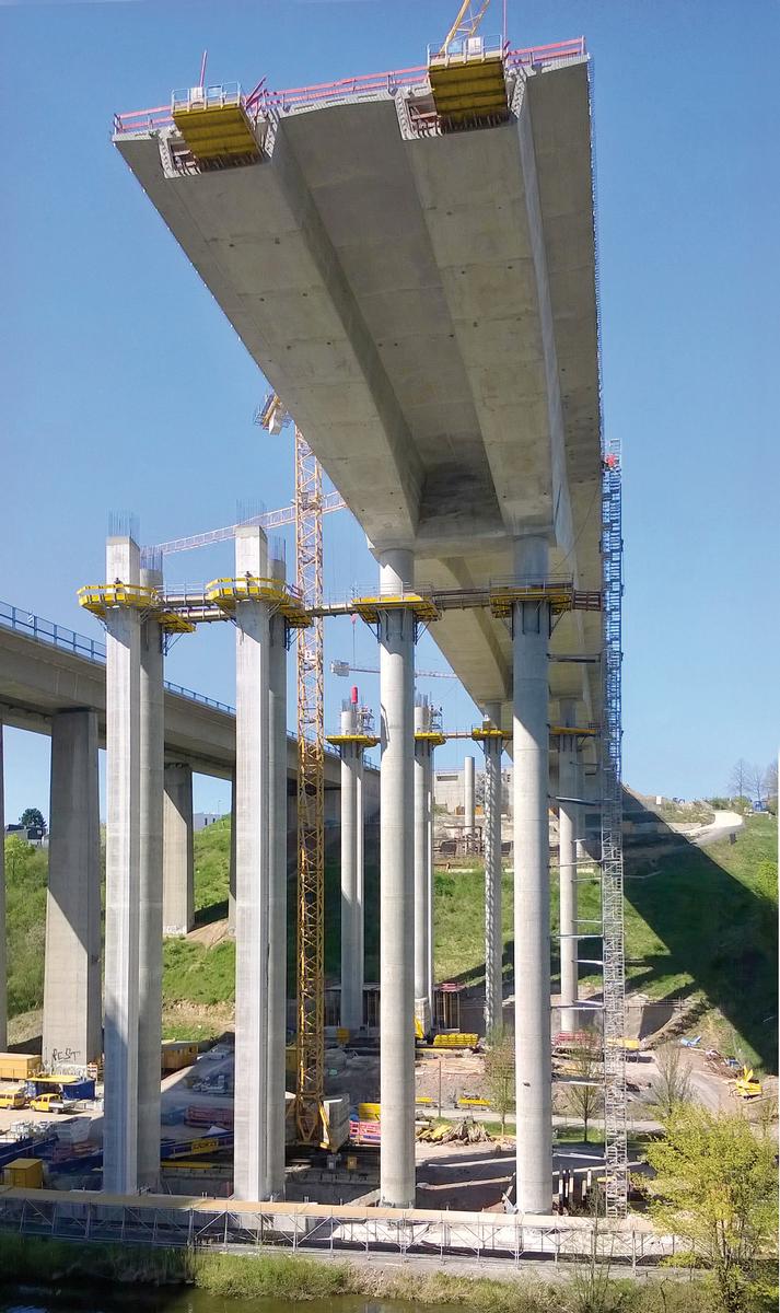
The beam bridge, 450 m in length, is a design by the joint venture of "Bürogemeinschaft Konstruktionsgruppe Bauen" from Kempten and Munich-based architects "Architekturbüro Karl + Probst". The roadways are 62 m above the lowest point of the valley floor, the seven spans range from 45 to 90 m in length. No bridge pier had to be set in the waters of the River Lahn itself. Haunched, twin-cell pre-stressed concrete box girders form the superstructures. Pairs of super-slim, circular reinforced concrete columns will transfer the loads of the bridge. Maximum pier diameter is a mere 2.80 m, and the tallest piers stand 57 m high. Cantilevering method was used to construct the superstructures. Secondary pier structures provided additional stability for the build phase. Lead contractor is Max Bögl Stiftung & Co. KG. Doka was awarded the contract for the extensive formwork technology.
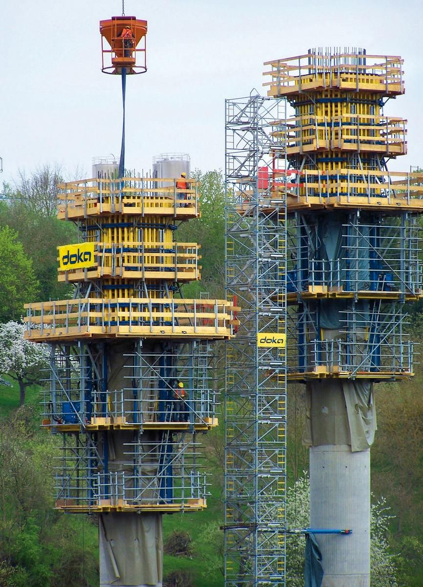
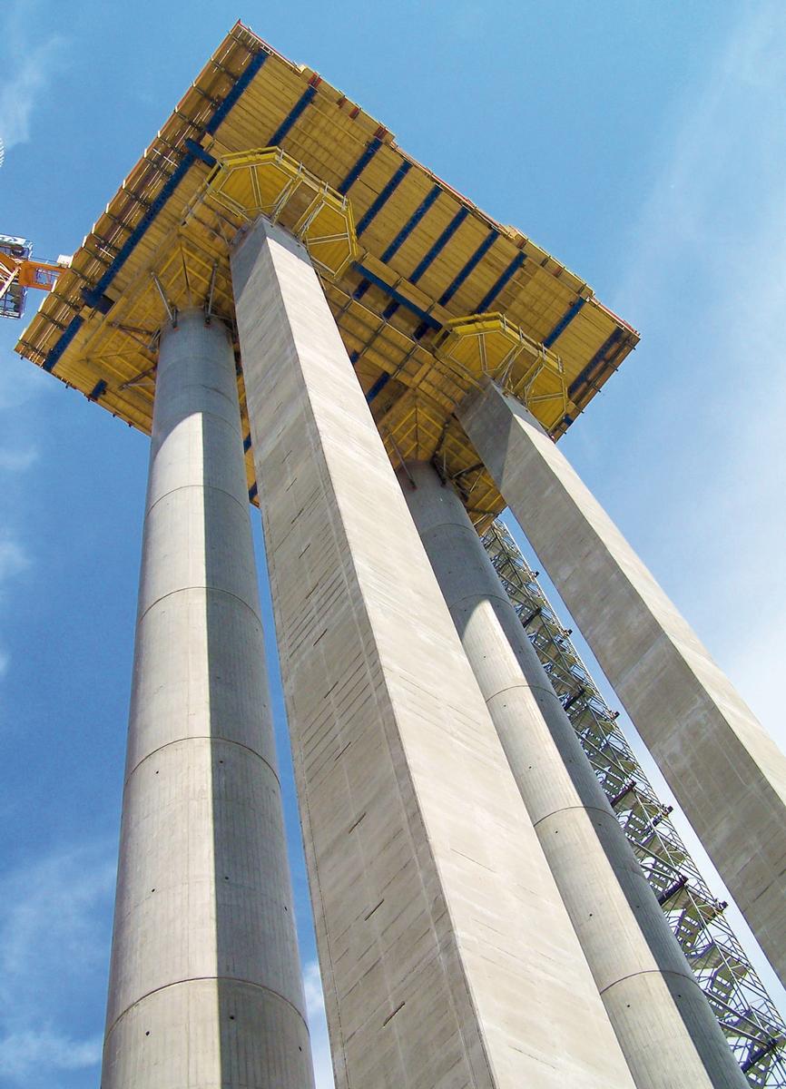
Climbing-system technology for the primary piers
An automatic climbing formwork was used to build the circular-section columns of the primary piers. The system climbed hydraulically and was anchored to the structure at all times by guiding shoes. So it could climb even when wind speeds were as high as 72 km/h. The panels consisted of timber formwork beams and steel walings. Maximum pouring height was 5.75 m at a formwork height of up to 6.00 m. Ladder systems with cages ensured safe up and down access between the three platform levels.
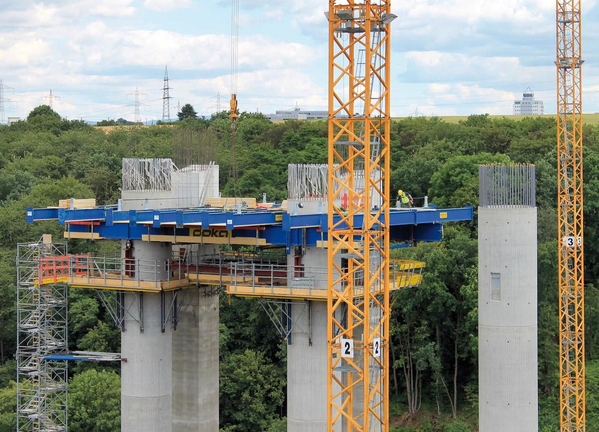
340 m² of workspace flat for pier heads
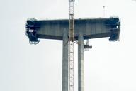
Asymmetric pier heads are the springers for cantilever construction. The pier heads were constructed on top of each pair of primary piers and were anchored into the adjacent pair of secondary piers. There are 675 m³ of concrete in each pier head. This corresponds to a concrete self-weight of just less than 1,700 metric tons – plus the weight of the reinforcement and the weight of the formwork. The pier heads were poured in three casting steps. The entire formwork solution for the pier heads plus falsework came from Doka, so everything was from a single source.
Two primary beams, each 20 m long, are the basis of each pier-head formwork structure. The secondary beams are ten coupled anchoring cross beams. Together they carried a closed workspace flat measuring 340 m² poised at heights up to 50 m above the valley floor. Pre-assembly of the bottom formwork units and the all-round guardrail systems was handled by Doka's pre-assembly service on site.
The bottom slab was the first construction section of the pier head. It has a self-weight of 437.5 metric tons and during its construction the steel-girder grilles slowly dropped about 10 cm. The bottom slab subsequently carries the weight of the second and third construction sections. The project owner had drawn up a set of detailed requirements for facing-board patterning, joins and visible finish of the pier heads. The facing boards for each of the eight pier heads were set by site. Comprehensive fall-protection systems were also needed at the exposed platform ends for the second and third concreting sections.
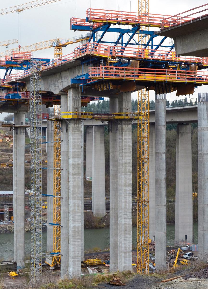
Secondary piers for added stability during construction
The superstructures of the new Lahntal viaduct were constructed toward each other from pier head to pier head. The cantilever forming travellers worked in pairs, so the horizontal forces acting on the bridge piers were always in equilibrium. Each pair of primary piers had two adjacent secondary piers. They stabilised the pier head at all times while cantilevering was in progress. The secondary piers had a cross-section of 2.0 x 2.0 m and were up to 50 m high.
The monolithic pier heads of the secondary piers had an integral pier reinforcement consisting of steel beams. These pier heads were formed with two sets of framed formwork. Eight sets of working platforms provided the all-important workplace safety. They were used as the work-deck level and as setdown areas for additional working scaffolds for the construction and subsequent dismantling of the secondary pier heads.
High-performing cantilever forming travellers
The cantilever forming travellers on the Lahntal viaduct each had four longitudinal trusses. They can handle varying section lengths from 3.75 to 5.00 m and concrete weights up to 250 metric tons. Complete with platforms the bottom grid was 9.50 m wide and 25 m long. With formwork and platforms, each of the four cantilever forming travellers weighed some 130 metric tons. First to last, initial assembly of the entire cantilever forming travellers was in the capable hands of the specialists from Doka's pre-assembly on site. A total of twelve complete repositionings of the cantilever forming travellers had to be handled as well. Doka also designed and built a special strand-jack platform using the Bögl company's own materials for cantilevering. This platform was used to hoist the bottom grids straight off the ground without the assistance of heavy-duty truck-mounted cranes.
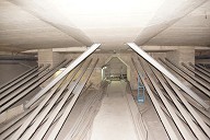
Through to the closing cycle, there was a 1.25 height variance at the bottom of the bridge's cross-section. So the bottom formwork telescoped in the area of the webs to allow for this difference. The inside formwork for the trough consisted of a drawer structure for speedy repositioning. When the cantilever forming traveller advanced an articulated carrier system automatically adjusted the bottom grid.
Unlike the typical cycles, the closing cycle had to be cast in two concreting sections. The bottom and the web were cast first. The top-slab rails of the cantilever forming traveller were then extended without any prior dismantling. The concrete was then cast for the roadway slab. When the closing cycle was completed, the cantilever forming carriage was brought back into position above the axis of the piers. Special retractors came into play at this stage of the procedure. With the carriage back at the piers, the bottom grid could be lowered. The carriage was then stripped down into big, largely undismantled repositioning units. Even the anchoring cross beams, more than 24 m in length, remained in place complete with the platform. At night, massive heavy-duty haulers manoeuvred the units into position for work on the other carriageway of the new bridge.
References

Structure Types


- About this
data sheet - Product-ID
7494 - Published on:
15/05/2017 - Last updated on:
29/05/2017