
General Information
| Name in local language: | Γέφυρα Ρίου-Αντίρριου "Χαρίλαος Τρικούπης" |
|---|---|
| Other name(s): | Rion-Antirion Bridge |
| Beginning of works: | 1999 |
| Completion: | 7 August 2004 |
| Status: | in use |
Project Type
| Structure: |
Multiple-span cable-stayed bridge |
|---|---|
| Function / usage: |
Motorway bridge / freeway bridge |
| Structure: |
Cable-stayed bridge with semi-fan system |
| Material: |
Steel-reinforced concrete composite bridge |
| Support conditions: |
for registered users |
| Plan view: |
Structurae Plus/Pro - Subscribe Now! |
| Material: |
Structurae Plus/Pro - Subscribe Now! Structurae Plus/Pro - Subscribe Now! |
| Secondary structure(s): |
Structurae Plus/Pro - Subscribe Now! Structurae Plus/Pro - Subscribe Now! |
Awards and Distinctions
| 2006 |
award winner
for registered users for registered users |
|---|---|
| 2005 |
award winner
for registered users |
Location
| Location: |
Rion, Achaea, West Greece, Greece Antirion, Aitolia-Acarnania, West Greece, Greece |
|---|---|
| Coordinates: | 38° 19' 1" N 21° 46' 31" E |
Technical Information
Dimensions
| total length | 2 880.400 m | |
| main bridge | ||
|---|---|---|
| main span | 560 m | |
| length | 2 252 m | |
| span lengths | 286 m - 3 x 560 m - 286 m | |
| number of spans | 5 | |
| deck | deck depth | 2.82 m |
| deck width | 27.20 m | |
| girder depth | 2.75 m | |
| pylons | pylon height (above deck) | 113.00 m |
Cost
| cost of construction | Euro 630 000 000 |
Materials
| deck |
composite steel-reinforced concrete
|
|---|---|
| piers |
reinforced concrete
|
Chronology
| 1880 | Harilaos Trikoupis, then prime minister of Greece, is among the first to imagine a link at this location. |
|---|---|
| 21 May 2004 | The last piece of the deck is mounted. |
|
Night of 7 August 2004
— 8 August 2004 |
In a grand ceremony including major fireworks, the bridge is officially inaugurated. |
| 8 August 2004 | Irina Szewinska from Poland and winner at the olympic games in Montreal and Mexico, Otto Rehagel, coach of the Greek soccer team that won the Euro 2004 championship, and Stratos Apostolakis, coach of the Greek Olympic soccer team, carry the Olympic flame across the bridge on its way to Athens for the Summer Olympics. |
| 12 August 2004 | The bridge is opened to traffic. |
| 2005 | Outstanding Civil Engineering Achievement (ASCE) |
| 28 January 2005 | One of the cables catches fire, possibly after being hit by lightning. The bridge is closed to traffic indefinitely in order to assess the damage. |
| 1 February 2005 | The bridge is re-opened to traffic, though use is limited to a single lane until the damage to the cable-stay has been repaired. |
| 2006 | Outstanding Structure Award (IABSE) |
| 2006 | Outstanding Concrete Structure Award (FIB) |
Notes
Concessionaire Gefyra and contractor Kinopraxia are composed of:
- Vinci (53%)
- J&P Hellas (11,2%)
- TEV (7,74%)
- Helleniki Technodomiki (7,74%)
- Athena (7,74%)
- Proodeftiki (7,74%)
- Sarandopoulos (7,74%)
Financing:
- Greek Government: 43%
- European Investment Bank: 47%
- Stock holder capital: 10%
Duration of construction: 5 years
Length of the concession: 42 years
The bridge is designed to withstand earthquakes of 7.5 on the Richter scale.
General
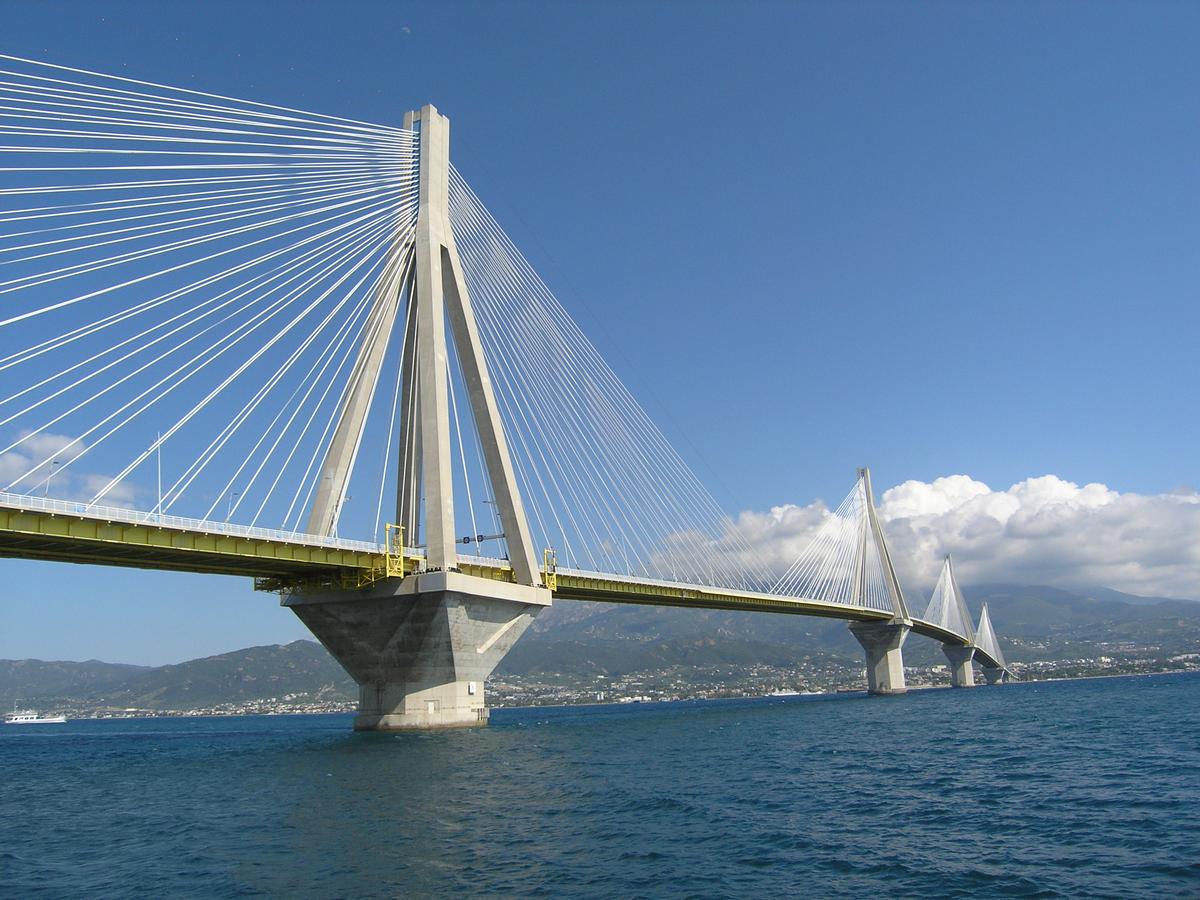
The Rion-Antirion Bridge crosses the Gulf of Korinth at its narrowest westerly location.
The design had to overcome some unusual problems. The difficult geology requires a minimum of piers. In the bridge region the sea is an average of 60 m deep, at places more than 65 m. The ground consists of a 20 – 30 m thick layer of clay, covered by a layer of sand and gravel of varying thickness. Rock is estimated only at about 800 m depth.
The whole region is subject to earthquakes with an intensity of 6.5 on the Richter scale. The maximum ground acceleration can reach 0.48 g, the corresponding maximum response acceleration in the bridge is 1.2 g in the eigenfrequency range of 1 – 5 Hz. In addition, horizontal and vertical tectonic dislocations of up to 2 m have to be considered. Although commercial ship traffic has a low density, the piers have to resist an impact of a 180 000 t oil tanker with a speed of 16 knots.
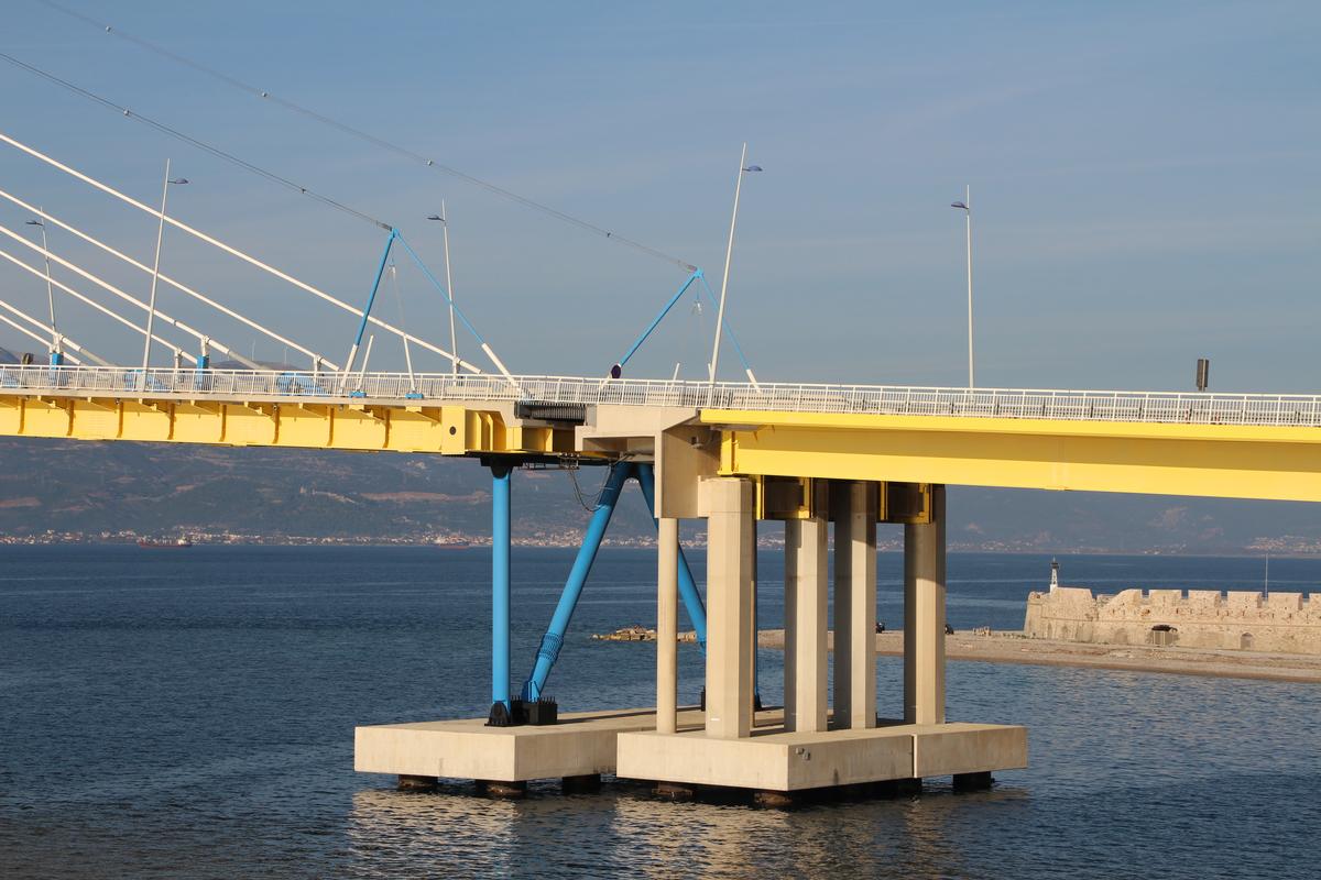
The main bridge has a length of 2 252 m with 2 880 m approaches on each side. The Rion-Antirion Bridge was designed by Jacques Combault. Michel Virlogeux was an important advisor.
Design
Based on the above conditions several alternate designs were considered in order to find the most economic solution. This led to a five-span cable-stayed bridge with three inner spans of 560 m and two side spans of 286 m.
A series of cable-stayed bridges of this size means a record for this type of bridge. The tower heads are stabilized by the four stiff tower legs with A-shapes in both directions. The beam is supported by 8 × 23 pairs of stay cables uniformly distributed over the length of the bridge. Vertically the beam is only supported on the two outer common piers with the approaches.
A detailed analysis of the interaction between foundations and superstructure showed that the beam, continuous over its full length and fully supported by stay cables, is able to adjust without permanent damage to the large possible horizontal and vertical tectonic dislocations of the towers.
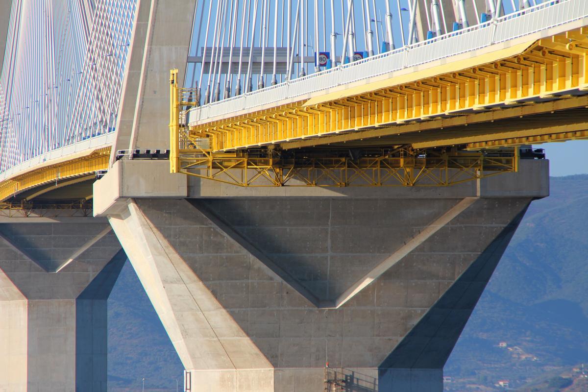
Beam
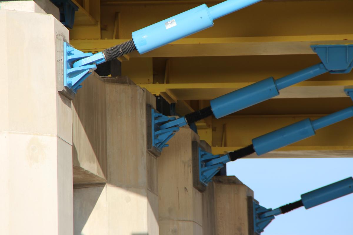
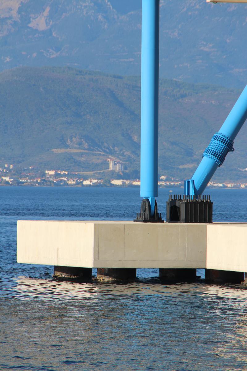
The 27.2 m wide composite bridge beam comprises two open steel main girders with a depths of 2.2 m (h : l = 2.2 : 560 =1 : 252), steel cross girders at a distance of 4 m, and a 24 cm thick concrete slab. All changes in lengths, due to temperature and tectonic dislocations, are only taken up at the ends by roadway joints with ± 2 m dilatation. In the transverse direction the beam is connected to each tower with four dampers.
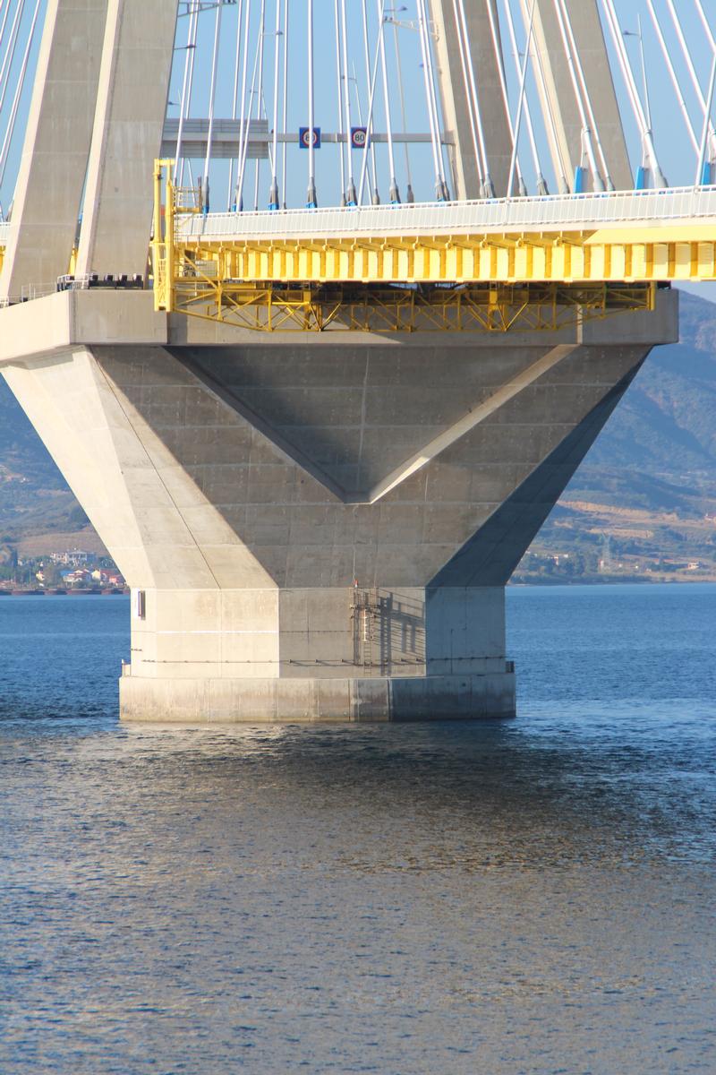
Foundations
The hollow reinforced concrete foundations with 89.5 m diameter are 9 m high at the outside and 13.5 m at the connection to the cone- shaped tower piers. At the inside they are stiffened by a torsion ring and radial beams. The foundations of the first three towers on the Rion side, which have a depths of 35 m, are directly resting on a gravel base layer which is strengthened by steel piles. These piles are 25 – 30 m long and placed on a 7 m by 7 m grid on a circular area of 130 m diameter. The base layer on top of the steel piles consists of a precisely leveled layer of gravel. The steel pipes are not directly load-bearing. They assist in distributing the tower loads into the ground and in limiting differential settlements. The gravel layer has to transfer the horizontal loads from the bridge onto the steel piles and surrounding ground plastically, thereby avoiding a failure plane in the clay layer.
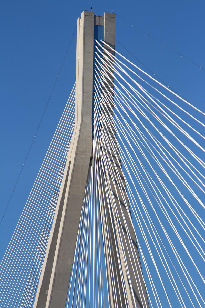
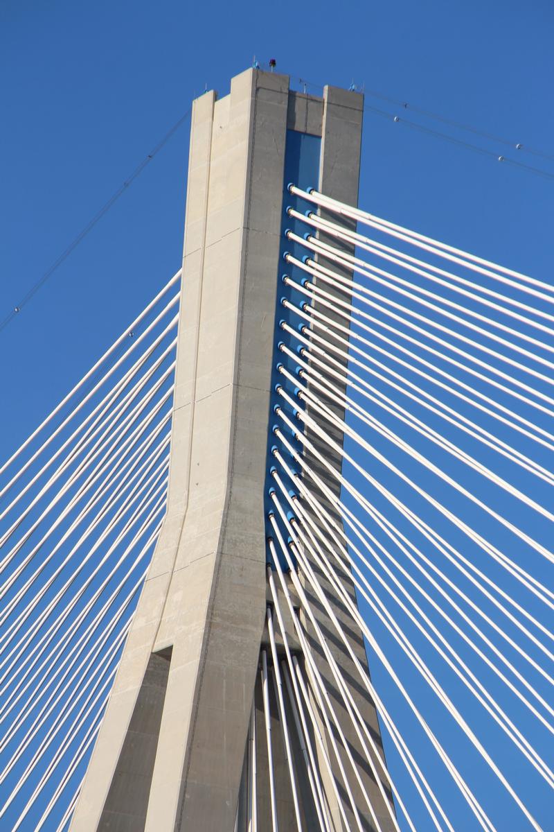
Towers
The concrete towers comprise a three-part pier with the tower legs above. A cone-shaped lower part with a diameter of 37.99 m at the base and 26.93 m at the top is fixed to the foundation. On it rests an octagonal shaft, 28.4 m high, with a pyramid-shaped 19.3 m high part on top. The tower legs have cross-sections of 4 m × 4 m. The tower head for the cable anchorage is composite with a steel box cast into concrete.
Stay cables
For the Rion-Antirion Bridge parallel strand cables were, as usual today, selected. At the beam they are anchored above the roadway at a web extension. At the tower heads theyconverge into composite anchorages.
Earthquake
The conditions for earthquake are based on a response spectrum on the ground with a 2000-year return period. The highest ground acceleration comes to 1.2 g over a range of eigenfrequencies between 1 and 5 Hz. There is no connection between the steel piles on ground and the foundation of the towers. The tower foundations can thus move against the layer of gravel strengthened by the steel piles. This new foundation concept extended here to earthquake-prone regions. The upper border of the load-bearing capa city of the strengthened foundations was developed by applying yield theory with appropriate kinematic mechanisms.
Non-linear finite element calculations were executed based on the above. The dynamic investigation of the bridge showed that the largest oscillations from earthquakes resulted in a multitude of cracks along the tower legs under the combined action of bending and tension. This cracked stage is, on one hand, helpful because it increases the flexibility of the legs below yield. On the other hand it is difficult to define precisely the cracked and uncracked regions during tower oscillations. As a consequence, 13 cross-sections were calculated in time steps of 0.02 sec which resulted in 130 000 different stages which all had to be investigated. An amplification factor made it possible to differentiate the individual steps by taking into account the behavior of the whole group of towers. At the same time the safety against progressive collapse of the whole group of towers was proved, in order to prevent a collapse of the whole bridge should one pier fail. The beam is continuous over the complete bridge length. At the towers an earthquake protection system is located transversely between the beam and the tower legs. It comprises dynamic dampers and hold-back systems with desired failure joints. These desired failure joints have to fail for earthquake forces above the highest wind loads in order to activate the hydraulic dampers which dissipate the energy and limit the transverse oscillations of the beam. The capacity of each of the four dampers at each tower comes to 3 500 kN in tension and compression. The relative movements between beam and towers during a designed earthquake reach ± 1.3 m with corresponding accelerations above 1 m/sec. For the approach bridges a combination of elastic isolators and hydraulic dampers was used.
Construction
Placing gravel layer
The particular difficulties for the construction of the piers are the large water depth of up to 65 m for the main piers, and the poor soils conditions. A combination of the latest technologies for off-shore oil platforms and submerged tunnels was used. The foundation works started with dredging the upper ground layer, placing a 19 cm thick layer of sand and ramming of the steel piles. The piles protrude 1.5 m above the sand layer and were covered with another 2 m thick layer of rounded river aggregates with a 50 cm layer of broken aggregates on top. This grading of gravel with decreasing inner friction from above to below provides the desired plastic behavior during earthquake. All these works were done from a 60 m long and 40 m wide floating platform which was anchored with chains to removable concrete blocks on the sea bottom. The equipment for piling was located on a submersible pontoon connected to one side of the platform with steel levers.
Foundations
The foundations for the towers were built in two steps near the city of Antirion. In a dry dock, 230 m long and 100 m wide, two circular foundations were concreted at the same time. The rear part of the dry dock had a depth of 8 m, the front part of 12 m. After completing the front foundation with a first pier section of 3.2 m the dry dock was opened by removing the front coffer dam and by towing foundation out. The second foundation was then towed forward and initially used to close the dry dock again. With this trick a lot of time was saved against the standard method of closing the coffer dam again. The construction of the pier shaft on top of the towed foundation was built in sections with jumping forms. After reaching the required height each foundation was towed to its final location and lowered onto the prepared gravel foundation. The whole foundation was then flooded in order to accelerate the expected settlements of 20 – 30 cm.
Towers
The four octagonal shafts were built in 4.8 m high sections with jumping forms. Heavy truss girders between the freestanding legs provided the required safety against earthquake during construction. The steel core for the cable anchorages in the tower heads was lifted in prefabricated units by a floating crane.
Beam
The composite beam was pre-assembled in 12 m long units, and the concrete roadway slab was cast on top, which is quite unusual. These 270 t elements were lifted by floating crane to the already built-in beam. The main girders were then connected with highstrength bolts, and the joints in the concrete roadway slab were closed with overlapping reinforcement and CIP concrete
Completed bridge
The Rion-Antirion Bridge represents a milestone in the development of cable-stayed bridges. Very difficult foundation conditions together with the high danger of earthquakes had to be overcome. Similar wide waterways may in the future be tackled with confidence following the example of the Rion-Antirion Bridge.
Excerpt from: Svensson, Holger Cable-Stayed Bridges, Wilhelm Ernst & Sohn Verlag für Architektur und technische Wissenschaften GmbH, Berlin (Germany), ISBN 343302992X; pp. 418-425. References to figures and literature were omitted.
Excerpt from Wikipedia
The Rio–Antirrio Bridge (Greek: Γέφυρα Ρίου-Αντιρρίου), officially the Charilaos Trikoupis Bridge, is one of the world's longest multi-span cable-stayed bridges and longest of the fully suspended type. It crosses the Gulf of Corinth near Patras, linking the town of Rio on the Peloponnese peninsula to Antirrio on mainland Greece by road. It opened one day before the Athens 2004 Summer Olympics, on 12 August 2004, and was used to transport the Olympic Flame.
Location
The 2,380-metre-long (7,808 ft) bridge (approximately 1.8 miles) dramatically improves access to and from the Peloponnese, which could previously be reached only by ferry or via the isthmus of Corinth in the east. Its width is 28 m (92 ft) — it has two vehicle lanes per direction, an emergency lane and a pedestrian walkway. Its five-span four-pylon cable-stayed portion of length 2,252 m (7,388 ft) is the world's third longest cable-stayed deck; only the decks of the Jiaxing-Shaoxing Sea Bridge in Shaoxing, China and the Millau Viaduct in southern France are longer at 2,680 m (8,793 ft) and 2,460 m (8,071 ft), respectively. However, as the former has a shorter length of main span (the length of the main span is the most common way to rank cable-stayed bridges, as the size of the main span does often correlate with the height of the towers, and the engineering complexity involved in designing and constructing the bridge) and as the latter is also supported by bearings at the pylons apart from cable stays, the Rio–Antirrio Bridge deck might be considered the longest cable-stayed "suspended" deck in the world.
This bridge is widely considered to be an engineering masterpiece, owing to several solutions applied to span the difficult site. These difficulties include deep water, insecure materials for foundations, seismic activity, the probability of tsunamis, and the expansion of the Gulf of Corinth due to plate tectonics.
Construction
Charilaos Trikoupis was a 19th-century prime minister of Greece who suggested building a bridge in the current location but the wealth of Greece at the time didn't permit its construction.
The bridge was planned in the mid-1990s and was built by a French-Greek consortium led by the French group Vinci SA which includes the Greek companies Hellenic Technodomiki-TEV, J&P-Avax, Athena, Proodeftiki and Pantechniki. The consortium operates the bridge under concession under its ΓΕΦΥΡΑ or ΓαλλοΕλληνικός Φορέας Υπερθαλάσσιας ζεύξης Ρίου-Αντιρίου (GEFYRA—Greek for "bridge"—or GalloEllinikós Foréas Yperthalássias zéfxis Ríou-Antiríou, French-Greek Carrier of Oversea Connection of Rio–Antirrio) subsidiary.
The lead architect was Berdj Mikaelian. Site preparation and dredging began in July 1998, and construction of the massive supporting pylons in 2000. With these complete in 2003, work began on the traffic decks with the steel fabrication being carried out by Cleveland Bridge U.K. and supporting cables by Freyssinet. On 21 May 2004 the main construction was completed; only equipment (sidewalks, railings, etc.) and waterproofing remained to be installed.
The total cost of the bridge was about €630 million, funded by Greek state funds, the consortium and loans by the European Investment Bank. It was finished ahead of its original schedule, which had foreseen completion between September and November 2004, and within budget. Other sources talk about €839 million.
Inauguration
The bridge was inaugurated on 7 August 2004, a week before the opening of the 2004 Summer Olympics in Athens. Olympic torchbearers were the first to officially cross it. One of them was Otto Rehhagel, the German football coach who won the Euro 2004 Championships for Greece. Another was Costas Laliotis, the former Minister of Public Works during whose term the project had begun.
Engineering feats
Due to the peculiar conditions of the straits, several unique engineering problems needed to be considered and overcome. The water depth reaches 65 m, the seabed is mostly of loose sediment, the seismic activity and possibility of tectonic movement is significant, and the Gulf of Corinth is expanding at a rate of about 30 mm a year. In addition, the hills on either side create a wind tunnel where 70 mph winds are common.
For these reasons, special design and construction techniques were applied. Beneath each pier the seabed was first reinforced and stabilized by driving 200 hollow steel pipes vertically into the ground. The pier footings were not buried into the seabed, but rather rest on a bed of gravel meticulously leveled to an even surface (a difficult endeavor at this depth). During an earthquake, the piers can move laterally on the sea floor with the gravel bed absorbing the energy. The bridge decking is connected to the pylons using jacks and dampers to absorb movement; too rigid a connection would cause the bridge structure to fail in the event of an earthquake and too much lateral leeway would damage the piers. There is also provision for the gradual widening of the strait over the lifetime of the bridge. Protection from the effect of high winds on the decking is provided by the use of aerodynamic spoiler-like fairing and on the cables by the use of spiral Scruton strakes.
The bridge received the 2006 Outstanding Structure Award from the International Association for Bridge and Structural Engineering. In 2006 the bridge was featured in an episode of Megastructures on the National Geographic Channel. In 2011 the bridge returned to TV in an episode of Richard Hammond's Engineering Connections. In 2015, construction of the bridge was chronicled in the first episode of the Science Channel series Impossible Engineering.
Trouble with cable links
On 28 January 2005, six months after the opening of the bridge, one of the cable links of the bridge snapped from the top of the M1 pylon and came crashing down on the deck. Traffic was immediately halted. The first investigation claimed that a fire had broken out on the top of the M1 pylon, after a lightning strike in one of the cables. The cable was immediately restored and the bridge reopened.
Monitoring system
A structural health monitoring system was installed during construction on the bridge. Still operating, it provides a 24/7 surveillance of the structure. The system has more than 100 sensors, including:
- 3D accelerometers on the deck, pylons, stay cables, and on the ground to characterize wind movements and seismic tremors
- Strain gauges and load cells on the stay cables and their gussets
- Displacement sensors on the expansion joints to measure the thermal expansion of the deck
- Water-level sensors on the pylon bases to detect infiltration
- Temperature sensors in the deck to detect freezing conditions
- Linear variable differential transducer (LVDT) sensors on the stay cables to measure movement
- Load cells on the restrainers for recalibration in the event of an earthquake
- Two weather stations to measure wind intensity, direction, air temperature, and relative humidity
One specific element of the system is the ability to detect and specifically treat earthquake events.
Text imported from Wikipedia article "Rio–Antirrio Bridge" and modified on June 3, 2020 according to the CC-BY-SA 4.0 International license.
Participants
- Berdj Mikaelian (architect)
- DOMI S.A. (approach viaduct Antirion)
- Michel Virlogeux (consultant)
- Jacques Combault (consultant)
- Buckland & Taylor Ltd.
- Denco S.A.
- FaberMaunsell
- Langan Engineering and Environmental Services, Inc.
- Parsons Transportation Group
- Ingérop
- Vinci Construction Grands Projets
- Jean-Marc Tourtois (construction engineer)

- Gilles de Maublanc (overseeing engineer)

Relevant Web Sites
-
Bernd Nebel: Harilaos-Trikoupis-Brücke

-
Info Grèce: Pont Charilaos Trikoupis: le colosse de Rio

-
Le Monde: conférence UTLS: Le pont de Rion-Antirion en Grèce, le défi sismique par Alain Pecker
-
Planète TP: Le pont de Rion-Antirion
-
Road Traffic Technology: Rion-Antirion Cable-Stayed Bridge, Greece

-
The Rion-Antirion Bridge

-
Wikipedia: Rio–Antirrio Bridge
Relevant Publications
- Les acteurs du projet. In: Travaux, n. 809 (June 2004), pp. 89.
- (2004): Adjustment of the Rion-Antirion Cable-Stayed Bridge. An Innovative Multidisciplinary Response to a Construction Challenge. Presented at: 1st FIG International Symposium on Engineering Surveys for Construction Works and Structural Engineering, The University of Nottingham, United Kingdom, 28 June - 1 July 2004.
- (2010): The Behavior of Rion - Antirion Bridge Seismic Protection System During the Earthquake of "Achaia-Ilia" on June 8, 2008. Presented at: IABSE Symposium: Large Structures and Infrastructures for Environmentally Constrained and Urbanised Areas, Venice, Italy, 22-24 September 2010, pp. 306-307.
- (2001): Bridge Builders Tackle Olympian Challenges. In: Engineering News Record (8 January 2001).
- (2002): Bridges - Ponts - Brücken. Atrium, Mexico City (Mexico), pp. 514-519.
- About this
data sheet - Structure-ID
20001110 - Published on:
19/10/2000 - Last updated on:
19/03/2017


