
General Information
| Completion: | June 2013 |
|---|---|
| Status: | in use |
Project Type
| Structure: |
U-shaped girder bridge Haunched girder bridge |
|---|---|
| Support conditions: |
for registered users |
| Function / usage: |
Bicycle and pedestrian bridge |
| Material: |
Weathering steel bridge Structurae Plus/Pro - Subscribe Now! |
| Plan view: |
Structurae Plus/Pro - Subscribe Now! |
Awards and Distinctions
| 2015 |
entry
for registered users |
|---|
Location
| Location: |
Leverkusen, North Rhine-Westphalia, Germany |
|---|---|
| Address: | Bahnallee / Werkstättenstraße |
| Connects to: |
Bridge Park and Western Ramp for the Campus Bridge (2020)
|
| Coordinates: | 51° 3' 47.80" N 7° 0' 33.55" E |
Technical Information
Dimensions
| span lengths | 23.6 m - 23.0 m - 12.8 m - 18.4 m - 22.9 m | |
| number of spans | 5 | |
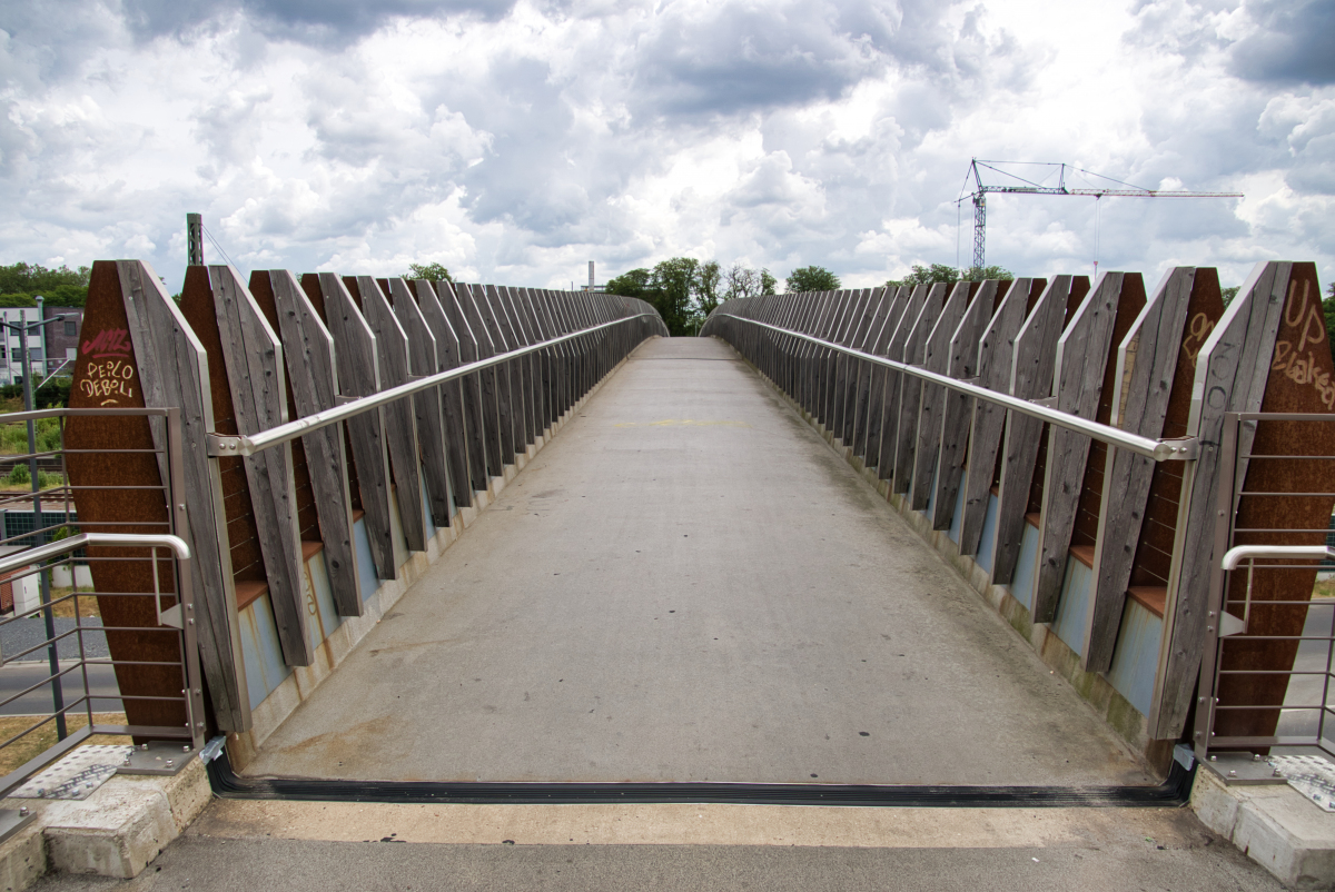
| walkway width | 3.00 m |
Cost
| cost of construction | ca. Euro 2 000 000 |
Materials
| deck |
weathering steel
|
|---|---|
| piers |
reinforced concrete
|
| abutments |
reinforced concrete
|
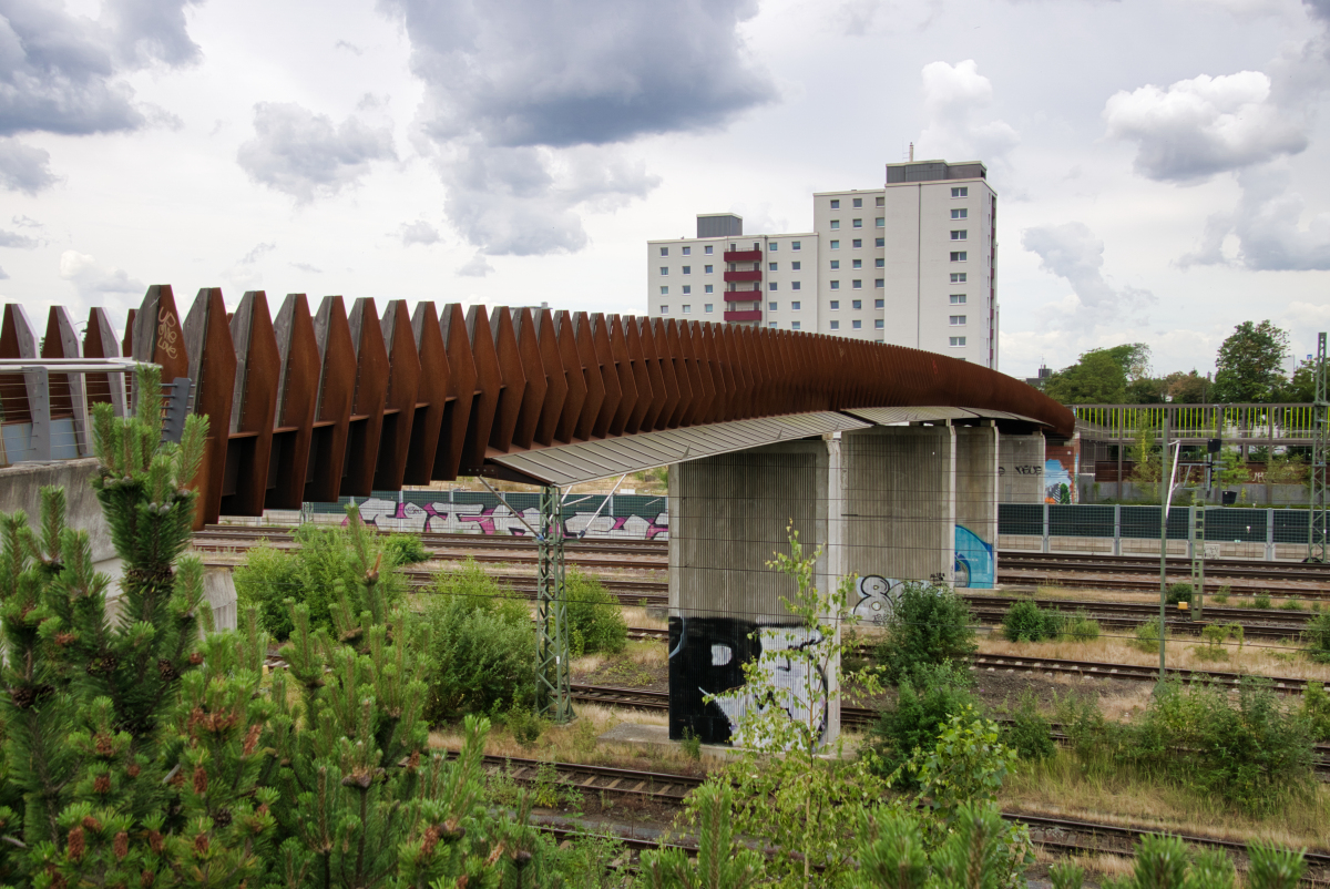
Pedestrian and cycle bridges in the new railroad town of Opladen
A new bridge family made of weatherproof steel
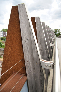
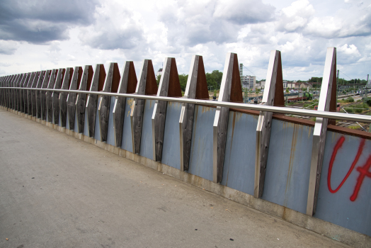
1 Structural design concept: restriction and variance
Bridge support structures over railroad facilities must meet very restrictive boundary conditions. For example, crossing electrified rail lines requires relatively high clearances to be maintained. Supporting structures at the bottom would further increase the level of the deck and thus the required ramp lengths. In the chosen concept of the trough bridge, the necessary static height is also used as a design element. The geometry of the side stringers is designed affine to the bending moment, with the maximum height in the center of the span varying according to the respective span; the load-bearing behavior becomes readable.
Assembly of superstructures over operating railroad tracks can only take place during short track closure periods coordinated with a long lead time. Structural concepts that require temporary support for intermediate conditions thus significantly increase the assembly and securing effort. The bridge spans are therefore designed as fully prefabricated single span girder segments.
2 Geometry development
The bridge segments have been developed based on pre-determined design-functional and structural-construction aspects using parametrically controlled geometry models.
The 3D models were built in Rhino 4 software from Mc Neal or with the help of the Grasshopper plug-in. All elements, based on the bridge radius, were deposited with mathematical definitions, which are defined by the system points of the abutments, the clearance profiles and the maximum permissible longitudinal inclination. The column positions, which are located centrally in the narrow corridors between the tracks, divide the longitudinal axis of the bridge into individual spans of different lengths. The statically necessary height of the side stringers is derived from the respective spans.
In addition to the geometry of the load-bearing trough cross-section, shape studies were prepared for the height and inclination of the slats. Thus, by changing individual parameters, a large number of models with different slat spacing, –heights and inclinations, wave shapes, etc. could be created and compared in a very short time.
The geometry models were transferred via specially programmed interfaces to the structural analysis software (Sofistik); where, with the help of FEM surface models, the load-bearing behavior was further investigated. In an iterative process, the load-bearing behavior could thus be optimized by the static calculations by adjusting individual parameters in the geometry model.
The geometry transfer to the executing companies took place at a later stage; here, the system geometry was defined as a coordinate table and transferred to the executing companies. Thus, the parametrically developed data set forms the basis of CNC-controlled manufacturing.
3 Design
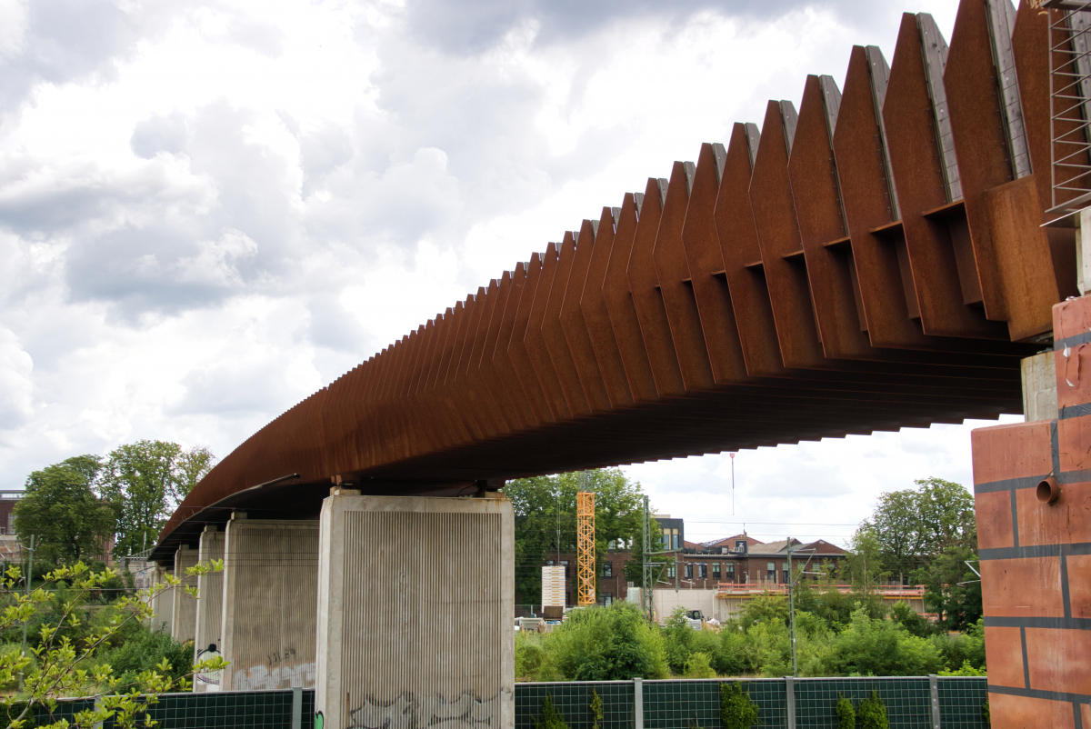
3.1 Superstructure
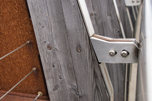
The bridge superstructure consists of two main girders, which are connected by transverse ribs and deck to form a trough cross-section. At the supports, the main girders, designed as welded Z-sections, have a vertical measured height of 550 mm and a maximum height in the center of the span of 1200 mm. The top flange has a static width of 220mm and a thickness of 12mm. An 8 mm thick deck plate acts as the bottom flange. The top and bottom flanges are connected by a 10 degree outwardly inclined 8mm thick web plate. For the design of the construction material „weather-resistant steel“ for the superstructure, an abrostrate of 1mm is assumed circumferentially for the cross sections in the calculations. The verifications are then carried out for the critical net or gross cross-section in each case. Only flat steel S355 J2 W +N (hot rolled) according to DIN EN 10025-5 is used.
To prevent buckling of the web plates and to support the top flange against lateral deflection, the distinctive stiffening ribs are provided at regular intervals, which also pass under the bridge and form the transverse ribs of the orthotropic deck. The thickness of the plate is 10 mm. The spacing of the transverse ribs, which varies for the individual bridge spans, is a maximum of 620 mm. At the supports and bridge transitions, the transverse ribs are connected with a horizontally inserted plate to form a hollow section in order to absorb the higher stresses as end cross members and transfer them to the support pair.
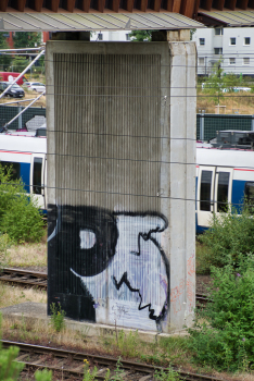
3.2 Substructure
The superstructure is supported by elastomeric bearings on the bridge piers and abutment walls. Reinforced concrete wall panels with dimensions of 4.00m x 1.20m serve as the central support of the superstructure. The dimensions result from the confined conditions in the track area and the resulting high train impact forces for high-speed trains that have to be taken into account. The piers are each aligned at right angles to the main girders and are founded on drilled piles.
4. Bridge approaches
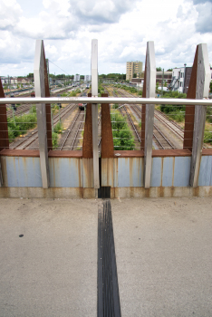
4.1 City balcony station bridge
The northern bridge is seemingly orthogonally „cut off“ in the area of the Opladen station building. The bridge ends at a height of about seven meters above the level of the street below. This conspicuous end – an obviously unfinished connection - becomes a symbol of the city's transformation that has begun.
In its current state, a „city balcony“ is created that invites people to watch the hustle and bustle around the Opladen train station and the city center. Once the current freight tracks have been dismantled, a public building is to be built directly adjacent to the bridge, which will take over the function of the vertical connection. Until then, a ramp construction as well as a stair tower with elevator will connect to the side of the bridge. In the tower, a steel staircase structure spirals around a reinforced concrete elevator core. Gevouted rectangular hollow sections cantilever outward from the reinforced concrete core to support the spiraling stair rails and walkway decking.
From the inside, the staircase is effectively illuminated, thus ensuring the functionally required brightness; at the same time, the vertical access structure appears in the dark as a striking prelude to the crossing.
4.2 Ramp structure Campus Bridge East
The area available for the ramp is located in direct extension of the local park "Green Cross", so the implementation of the driveway as a Aufenthalsqualitäten offering landscape structure was obvious. A step-like arranged green area, gently sloping towards the east, was filled up, which is bordered in three directions by gabions or retaining walls.
4.3 Temporary Bridge Access Campus Bridge West
At the west end of the campus bridge, other interim conditions need to be considered. After the freight track relocation, only the proposed railroad alley, a north-south running road with a low clearance, will need to be crossed. In the current state, however, the freight tracks running west of the abutment have to be crossed with a clearance gauge of a good seven meters. The problem was solved by a technical trick in the design of the bridge. The western abutment forms a plateau at about five meters above street level, i.e. the height in the final state after relocation of the freight line. In its final state, the westernmost bridge span is to slope down to this abutment at a 6% gradient. In the interim condition, however, this span is installed rotated by 180 degrees, the slope thus becomes an ascent, and the west sill of the span ends on a temporary platform 6.50m above the abutment plateau. From there, a short ramp and temporary bridge span leads over the aforementioned freight tracks and ends in an equally temporary spiral ramp of scaffolding erected in a parking lot.
Explanatory report by Knippers Helbig for submission to the Ulrich Finsterwalder Engineering Award 2015
Participants
Owner
Design
- Knippers Helbig GmbH
-
Knight Architects
- Martin Knight (architect)
Structural engineering
Contractor
Construction management

Site supervision
Relevant Web Sites


Relevant Publications
- (2022): Campusbrücke Opladen - Applying Sustainable Design Strategies within Changing Constraints. Presented at: Footbridge 2022: Creating Experience, Madrid, Spain, 07-09 September 2022.
- Two of a kind. In: Bridge Update, n. 83 (April 2009), pp. 4.
- (2014): Weathering steel footbridges over railway tracks - Campus Bridge in Opladen. Presented at: Footbridge 2014 - Past, Present & Future, London, 16-18 July 2014.
- About this
data sheet - Structure-ID
20048203 - Published on:
23/09/2009 - Last updated on:
06/08/2023
Structurae cooperates with


