

General Information
Project Type
| Structure: |
Cable-stayed bridge with fan system |
|---|---|
| Secondary structure(s): |
Structurae Plus/Pro - Subscribe Now! |
| Function / usage: |
Motorway bridge / freeway bridge |
| Material: |
Reinforced concrete bridge Structurae Plus/Pro - Subscribe Now! |
Awards and Distinctions
| 1996 |
Award of Merit
for registered users |
|---|
Location
| Location: |
Baytown, Harris County, Texas, USA La Porte, Harris County, Texas, USA |
|---|---|
| Crosses: |
|
| Carries: |
|
| Coordinates: | 29° 42' 15.47" N 95° 0' 58.11" W |
Technical Information
Dimensions
| total length | 4 185 m | |
| bridge surface | 32 800 m² | |
| main bridge | ||
|---|---|---|
| main span | 381 m | |
| length | 674.8 m | |
| span lengths | 146.9 m - 381.0 m - 146.9 m | |
| number of spans | 3 | |
| vertical navigation clearance | 54 m | |
| deck | deck width | 47 m |
| pylon | pylon height | 129.84 m |
Materials
| cables |
polymer-wrapped twisted steel wire bundles
|
|---|---|
| pylons |
reinforced concrete
|
| deck of main bridge |
reinforced concrete
|
| deck of approach viaducts |
precast prestressed concrete
|
Chronology
| 27 September 1995 | Official opening. |
|---|
Notes
The pylons were cast in place in increments of approximately 15'. The rebar cages were pretied on the ground in 34' segments and transported to the south pylon by a tractor trailer, and to the north pylon by a barge. The cages (weighing approximately 17 tons) Were then rotated from a horizontal to vertical position and raised into place, using a 4600 Manitowoc crane (lower portion), or Derrick crane (upper portion). The cages were lowered into position an were mechanically coupled with a hydraulically compressed malleable steel coupler (supplied by Dayton Barsplice Products, Dayton Ohio).
The tower anchor segments were also pretied, on the ground, around a plywood interior form (with steel anchors and post-tension ducts pre-installed). These segments were limited to approximately 10 tons (due to the capacity of the Derrick crane boom radius at this elevation).
The tower anchor segments were post-tensioned prior to cable stay installation.
The only elements on this bridge that were prestressed were the Type "V" ASSHTO concrete girders. (Approaches)
[Text provided by Glen Robinson (Rebar Superintendent)]
Design and Construction of Baytown Bridge
General layout
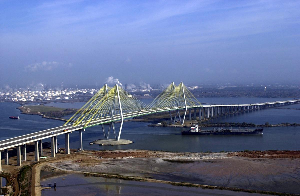
During the mid 1980s the existing tunnel underneath the Houston Ship Channel in Texas, USA, could not cope with the increased volume of road traffic and had to be replaced by a bridge. This large amount of traffic required four lanes with full shoulders in the each direction. A detailed investigation resulted in two independent beams as the most economic solution. The bridge crosses the Houston Ship Channel 32 km east of Houston between the cities of Baytown and LaPorte. The busy ship traffic between the Gulf of Mexico and Houston Harbor required a navigational clearance of 53 m. The towers were protected against ship collision by locating one of them on shore and the other one in shallow water and surrounding it with an artificial island. As usual for major bridges in the USA complete designs for a concrete and a steelcomposite alternate were tendered. The project was awarded for $ 91.3 m to the steelcomposite alternate outlined here. The bridge was designed in accordance with AASHTO, amended by other US and international codes. All structural parts were designed in service limit state and ultimate limit state. The concrete for the roadway slab was C 50 standard and for the tower C 42, the reinforcement had a yield strength of 420 N/mm² and the structural steel ultimate strength of 520 N/mm².
Bridge system
The cable-stayed bridge with a main span of 381 m has a beam continuous over 674.8 m and is symmetrically supported. The vertical and horizontal support loads are taken at the two towers and the hold-down piers. The beam and the anchor piers are connected by 305 mm diameter pins which also transmit uplift forces. The fixed point of the bridge is thus located in the center of the main span. The beam deformations due to change of temperature and shrinkage and creep are taken up by the neoprene bearing with horizontal shear deformations, and the anchor piers are slender enough to follow by deformations in bending. The beam rotations at the anchor piers are taken up by hinged roadway joints, the longitudinal movements of ± 380 mm are carried by additional movement joints at the ends of the short first approach spans. By distributing the rotations and translations onto two roadway joints on each side of the bridge their detailing is simplified and they become more robust. The movements of the superstructures are limited at the towers, longitudinally between short concrete corbels and transversely between buffers. The transverse wind forces are carried by central wind bearings in the middle of each end cross girder.
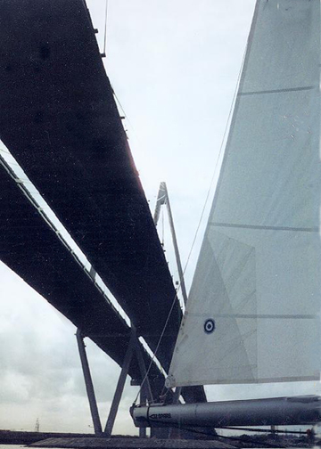
Composite beam
Structural detailing
Because of the large beam width required for four lanes in each direction of travel, systems with two, three and four cable planes were investigated. For two outer cable planes the amount of steel required in the transverse direction was as big as required longitudinally. Two independent beams with two cable planes each required only half the steel in the transverse direction and were thus selected as the most economic solution. Each composite beam comprises a concrete deck resting on a steel grid from open outside main girders and cross girders. For economic reasons the webs were selected in such a way that only one longitudinal stiffener was required in the middle of the main girders. The vertical stiffeners of the main girders at a distance of 5.2 m are welded to their top and bottom flanges in order to transmit the end moments of the cross girders, which are created by their torsional stiffness. Only in the region of high moments with changing signs in the bridge center and at the bridge ends are the vertical stiffeners bolted to the bottom flanges of the main girders for improved fatigue resistance. The concrete roadway slab consists of a 200 mm thick structural concrete layer covered by a 100 mm wearing layer, requested by the Texas State Highway Department for protection against a burning petrol truck in case of an accident. The cables are anchored at a distance of 15.2 m in welded boxes bolted to the webs of the main girders. Composite action between the steel grid and the concrete roadway slab is provided by shear studs protruding into the CIP joints. Together with the stay cables the anchorages are also exchangeable. The eccentricity moment between each cable axis and the main girder webs is carried by a force couple at the ends of the cable anchor box. The compression component is transmitted into the roadway slab, the tension component is transmitted into the bottom flange of a cross girder. The bottom of the anchor boxes is thus always located at a bottom flange of the cross girder. The cable distances thus vary slightly with the cable inclination. For the concentrated anchorage of the three backstay cables the main girder is widened to a box at the bridge ends. These boxes connect the regular open cross girders after a distance of 15 m. The box girder was necessary to achieve the required torsional stiffness in the 5.4 m long cantilevers protruding into the first approach span. They have a width of only 0.45 m and can thus not be inspected. They are therefore filled with lowshrink concrete.
Design calculations
The run of moments under permanent loads was chosen as that of a beam rigidly supported at the cable anchor points. In the center of the bridge and at the bridge ends positive moments were additionally introduced to create additional compression in the concrete roadway slab. The beam moments from life load increase up to 26% from non-linear effects (P-Δ effect) because of the high beam slenderness of 1:200. In case any cable has to be exchanged two loadings were investigated. For an anticipated loading, e.g. in the case of corrosion, the adjacent lane would be closed to traffic and increased stresses are permissible. In the case of a sudden loss of a cable, e.g. during an accident, no structural part is to suffer permanent deformations. The corresponding action forces were calculated by taking into account the torsional stiffness of the main girders supported transversely by the cross girders and the roadway slab. The roadway slab is permanently under compression from dead loads: transversely as bottom chord of the cross girders, longitudinally from the compression component of the inclined stay cables. In the center of the bridge and at the bridge ends, where the compression forces from the stay cables are small, frozen-in positive moments are introduced into the beam by cambering the shop form. As top flange of the composite beam these cambered moments cause additional permanent compression in the roadway slab. The crack widths from transient loads are limited by a substantial minimum reinforcement, consisting of bars Ø 18 mm and at a distance of 115 mm crosswise, equal to a minimum content of 2.2% reinforcement. The shear studs were designed for the combined action of shear from overall and local loads, introduction of cable force and local transverse bending. Assuming limited slip and plastic deformations in the ultimate limit state led to a uniform distribution of the shear studs over the length of the edge girder. The introduction of the shear forces from the 300 mm thick concrete edge slab into the 200 mm thick inner roadway slab, proved to be critical and was designed with a strut and tie model in the ultimate limit state.
Contractor’s alternate
In the tender design it was proposed to cast the roadway slab onto the girder grid in the pre-assembly yard before installation, in order to carry the concrete weight in the transverse direction by composite action. The contractor, however, shied away from lifting the corresponding 250 t elements and proposed to install the roadway slab from precast segments after the installation of the girder grid. The CIP joints were arranged on top of the cross girders; the shape of the joints was developed in collaboration between the engineers and the contractor. This joint makes it possible to connect the upper layer of reinforcement with straight lap splices for good crack distribution. In order to use the top flanges of the cross girders just as joint formwork, loop splices were used for the bottom layer of reinforcement. Due to the loss of composite action for the weight of the fresh concrete, auxiliary stiffeners were required for the installation of the girder grid. Their additional weight of 640 t increased the total quantity of steel for the girder by 17% from 121 kg/m² to 141 kg/m².
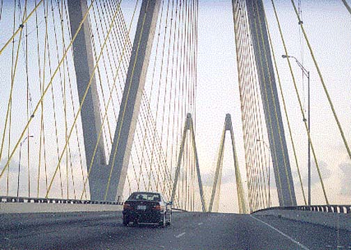
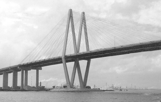
Towers
The concrete towers in double diamond shape have box cross-sections with minimum wall thicknesses of 305 mm over most of their height. The shape of the towers resulted from the two beams. The upper A-frames increase the rotational stiffness of the beams by forming a stiff three-dimensional truss together with the stay cables and the beam. This increases the important first torsional frequency of the beam considerably. By merging each pair of tower legs underneath the beam, the number of foundations is reduced to two. In this way each twin tower forms a complete truss which carries the horizontal loads from wind by tension and compression only. The widths of the tower legs can thus be reduced to 2.13 m, constant over the full height of the towers. In the longitudinal direction the towers act as a cantilever, especially during free cantilevering construction of the beam, and thus substantially greater dimensions are required. The ties underneath the beams carry the deviation forces from the kinks of the tower legs. They are fully post-tensioned. In the concrete tower head the stay cables run through cast-in steel pipes. The anchor heads rest on steel base plates and are secured in place by shims. The horizontal components of the cable forces are carried by staggered loop tendons.
Stay cables
The stay cables comprise 20–61 strands ø 15 mm with wedge anchorages at both ends. They are protected by thick-walled PE pipes and were grouted after installation. Wrapping of the PE pipes with UV-resistant self-adhesive yellow PVF tape reduces the temperature changes of the stay cables from direct solar radiation and improves the aesthetics of the bridge. In order to avoid simultaneous failure of the three closely spaced backstay cables at each end of the bridge, for example by a burning petrol truck, these cables were additionally protected by outer steel pipes with a length of 15 m, the 25 mm clear space between the PE pipes and the steel pipes was filled with grout. The stay cables were designed in accordance with the PTI guidelines. The cables were pre-assembled on the approach bridges.
Aerodynamic stability
The bridge is located in a hurricane-prone area. The wind design speed for a 100-year probability at 10 m height for a duration of 10 min. was assumed as 50 m/s. The ratio between the first eigenfrequencies in torsion and bending comes to fT / fB = 0.670 / 0.273 = 2.45. This favorably high value, in spite of the torsionally weak open beam cross-sections, was achieved by the use of A-towers. Wind tunnel tests with a section model scale 1:96 and a full model scale 1 : 250 as well as an independent analytical investigation by Bob Scanlan resulted in a critical flutter wind speed of more than 67 m/s. For a turbulence intensity of 12 %, the bridge beam oscillates with a double amplitude of 1.65 m from buffeting. The governing construction stage during cantilevering just before side span joint closures had critical wind speeds of only 47 m/s which was considered too low, taking into account the high hurricane probability. The beams were thus tied down during construction. The aerodynamic investigations showed that an energy transfer takes place between the oscillating windward beam and the leeward one, whereby energy is consumed. For the actual geometric and dynamic characteristics of this bridge the unconnected twin beams are less sensitive against wind excitation than the individual beams would be by themselves.
Construction
Foundations
Floating foundations are used in the alluvial soils around the Houston Ship Channel, where rock is found only in great depth. They consist of 130 Nos, 50 cm square and 40 m long prestressed driven piles. Load tests indicated a bearing capacity of 200 t during service. The 3.6 m deep pile cap was reinforced with several layers of bars with ø 40 mm.
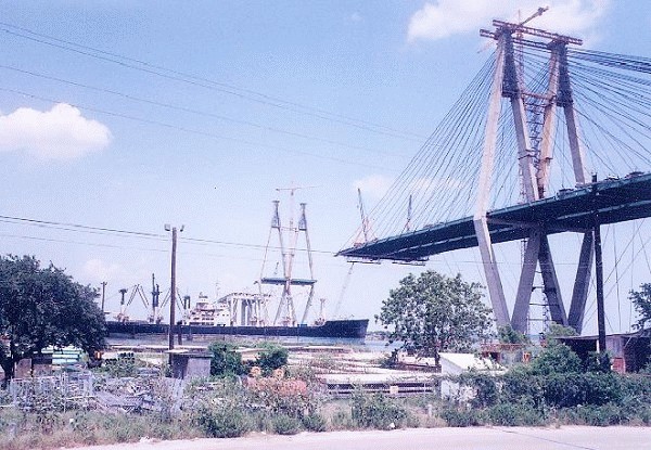
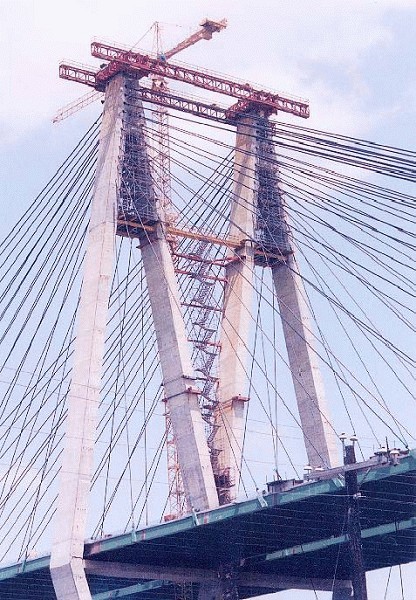
Towers
The tower legs were built by free cantilevering with jumping forms in 4.5 m sections. For the first tower a formwork truss was used covering its full width, on which two cranes were running. The relocating of the large steel truss proved to be difficult. Therefore, smaller individual jumping forms for each tower leg were used for the second tower. All tower legs had wall thicknesses of 305 mm and two layers of reinforcement at 150 m. At the intersection of the inner tower legs at beam level 220, reinforcement bars ø 25 mm from each side had to cross. This reinforcement was preassembled in a cage with a weight of 18 t on the ground and then lifted. The bars were coupled with squeezed sleeves. In spite of the dense reinforcement a successful casting was achieved by the use of gravel with ø < 16 mm and a super-plasticizer. In the tower head the stay cables run through cast-in steel pipes and their anchor heads are retained on compression plates resting on concrete. The forms for the cable anchorage area were built in sections on the ground with the steel pipes precisely located. Around the inner forms dense reinforcement was placed, so that the precise location of the cable anchorage points in space was ascertained. After concreting, the short overlapping loop tendons were stressed against the hardened concrete.
Beam
The steel grids for the beams were, for economic reasons, fabricated in Cape Town, South Africa. After shipment, the final corrosion protection was applied in the pre-assembly yard in Texas and the grid sections were then test bolted and surveyed. The first short starter elements of the beam in the tower axis were lifted with tower cranes. On them the derricks were installed with which all other beam elements were lifted. Above water the grid elements were delivered from the pre-assembly yard by barges and lifted to the beam by the derricks. Since no welding on site is acceptable in the USA even today, the main girders were connected with cover plates and high-strength bolts. (For this reason orthotropic decks are still not used in the USA today because they require field welding.) The precast slabs were also delivered by barges and lifted up by the derricks. The precast slabs span between the cross girders. The shear studs protrude from their top flanges into the slab joints. The joints were cast with low-shrink rapid-hardening joint concrete. They had cured before the next beam element was installed. The final beam sections in the side span are cantilevered into the first approach span. In them the concentrated three backstay cables are anchored. Before center joint closure the two cantilever tips were carefully surveyed to adjust the end piece to the actual conditions. This survey takes best place shortly before sunrise when the temperature gradient in the beam is equalized. Finally, the closure piece was lifted-in and bolted. During free cantilevering the fixed points of the beams were located at each corresponding tower. Before side span joint closure the beam was shifted outwards with jacks between the corbels at the towers, so that the neoprene bearings, were deformed to the outsides. Simultaneously the anchor piers were pushed 75 mm to the outside. After shrinkage and creep, the neoprene bearings and the anchor piers are supposed to end up vertically. The construction of the first half of the bridge was delayed substantially due to difficulties during fabrication of the steel grids. Originally the „Buy American Clause“ applied for the steel, which was lifted after these costs were too high, and the steel was procured and fabricated in South Africa. The second beam half, however, was built in only five months.
Stay cables
For economic reasons, parallel strand cables were selected by the contractor. They were delivered in their individual components. These were assembled on site and the completed stay cables were installed and stressed like completely shop-fabricated cables. The assembled stay cables are in accordance with the state-of-the- art of that time: 15 mm galvanized strands with anchorages in thickwalled black PE pipes, which are filled after installation with cement grout. The PE pipes were butt welded to their final lengths on the approach bridges and the strands were pulled into them. The ends of the strands were fixed with wedges to the anchor heads. At the passive anchorage at the beam, the wedges were finally pressure wedged and secured, whereas at the active stressing ends for the tower heads they were only pre-wedged. The pre-assembled stay cables were pulled to the main bridge supported by a highline. The pull rope up to the tower head was connected to a guide at the stay cable in order not to damage the PE pipe by too sharp bends. The cables were then lifted up to the tower heads. Since the anchor box and the bottom flange of the main girder did not allow the stay cables to be stressed at the beam anchorage, the anchor heads were inserted there and secured against slipping by shims. The inclination of the cable tip was precisely adjusted to the steel pipe at the end of lifting. Then the stay cables could be pulled into the tower head. Sufficient space was provided inside the tower head to install the jack chair and the hydraulic jack. A grip hoist at the end of the jack pulled the cable close enough so that the protruding strands could be gripped by the jack. After final stressing and grouting of the stay cables they were wrapped with a yellow, UV-resistant PVF tape for aesthetic reasons.
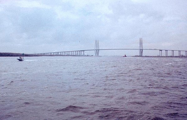
Completed bridge
The bridge was opened for traffic on 27 September 27 1995, and named the Fred-Hartmann-Bridge. The completed bridge was honored with several awards, including the Federal „Presidential Award“, the highest bridge prize in the USA and the „Outstanding Civil Engineering Award“ for 1996.
Excerpt from: Svensson, Holger Cable-Stayed Bridges, Wilhelm Ernst & Sohn Verlag für Architektur und technische Wissenschaften GmbH, Berlin (Germany), ISBN 343302992X; pp. 387-401. References to figures and literature were omitted.
Excerpt from Wikipedia
The Fred Hartman Bridge is a cable-stayed bridge in the U.S. state of Texas spanning the Houston Ship Channel. The bridge carries 2.6 miles (4.2 km) of State Highway 146 (SH 146), between the cities of Baytown and La Porte (east of Houston). The bridge is also expected to carry State Highway 99 (SH 99) (Grand Parkway) when it is completed around Houston.
The bridge, named for Fred Hartman (1908–1991), the editor and publisher of the Baytown Sun from 1950 to 1974, is the longest cable-stayed bridge in Texas, and one of only four such bridges in the state, the others being Veterans Memorial Bridge in Orange County, Margaret Hunt Hill Bridge in Dallas and Bluff Dale Suspension Bridge in Erath County. It is the 77th largest bridge in the world. The construction cost of the bridge was $91.25 million.
The bridge replaced the Baytown Tunnel (of depth clearance 40 feet or 12.2 m). The tunnel had to be removed when the Houston Ship Channel was deepened to 45 feet (13.7 m), with a minimum 530 feet (161.5 m) bottom width, to accommodate larger ships. The last section of the Baytown Tunnel was removed from the Houston Ship Channel on September 14, 1999, with removal of the tunnel being the responsibility of the Texas Department of Transportation (TxDOT).
Construction
In October 1985 the Texas Highway department announced the project and estimated it would take two years to complete. The bridge was designed by Greiner Engineering, Inc., which was acquired by URS Corporation in 1995, which in turn was acquired by AECOM in October 2014. Construction began in 1987 and was contracted by Williams Brothers and Traylor Brothers construction companies. In 1993, The firm selected to produce the steel, a Mexican company, went bankrupt. The contract was then awarded to a South African company which caused complaints because of the country's apartheid policies. After the completion date was pushed back several times, a letter was sent to the Texas Department of Transportation's executive director, William Burnett from the city of Baytown via the Baytown Sun in early 1995 which helped spur interest in finishing the project. Finally, on September 27, 1995 the Fred Hartman Bridge had its grand opening ceremony, which was hosted by Baytown Chamber of Commerce and La Porte Chamber of Commerce. Notable guests include George W. Bush, Miss Texas 1995, William Burnett and the Hartman family. Fred Hartman died in 1991 and did not live to see his dream come to fruition.
The possibility of placing tolls on the bridge became an issue in a runoff election for the Texas House of Representatives in 2016 between the Republican winner, attorney Briscoe Cain of Deer Park, and the defeated seven-term Representative Wayne Smith of Baytown. Cain claimed that an online petition opposing tolling of the structure was a "preventative measure" because, "Smith's work history and legislative record on transportation gives Texans plenty to be concerned about." Bob Leiper, a former city manager in Baytown, leaped to Smith's defense in a "Letter to the Editor" of the Baytown Sun: I was astounded by Briscoe Cain's claim that Rep. Wayne Smith is somehow trying to make the Hartman Bridge a toll bridge. As an attorney you would think he would seek the truth before making such a wild claim and blaming it on one of the best friends and advocate Baytown ever had in Austin.
Text imported from Wikipedia article "Fred Hartman Bridge" and modified on 28 October 2020 according to the CC-BY-SA 3.0 license.
Participants
Owner
Original design
Wind analysis
- Robert H. Scanlan (consultant)
Structural engineering
- DRC Consultants
-
Leonhardt, Andrä und Partner
- Holger S. Svensson (structural engineer)
Co-contractor
Cables

Cable maintenance (2014-2015)
Cable repairs
Relevant Web Sites

Relevant Publications
- (2002): 30 Bridges. Laurence King, pp. 100-103.
- : 30 Brücken. Callwey Verlag, Munich (Germany), pp. 100-103.
- (1993): Bridges. Macmillan Publishing Company, New York (USA), pp. 135.
- (2007): Cable Vibrations in Cable-Stayed Bridges. International Association for Bridge and Structural Engineering (IABSE), Zurich (Switzerland), ISBN 978-3-85748-115-4, pp. 114-119.
- (2013): Cable-Stayed Bridges. 40 Years of Experience Worldwide. Wilhelm Ernst & Sohn Verlag für Architektur und technische Wissenschaften GmbH, Berlin (Germany), ISBN 978-3-433-02992-3, pp. 387-401.
- About this
data sheet - Structure-ID
20000555 - Published on:
21/11/1999 - Last updated on:
05/02/2016
Structurae cooperates with


