
Emirates Air Line (London Cable Car)
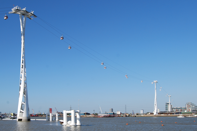
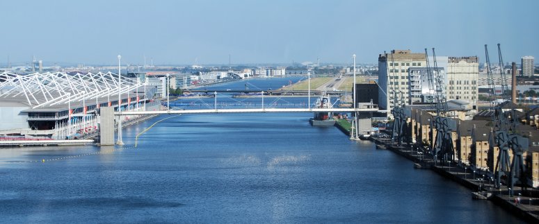
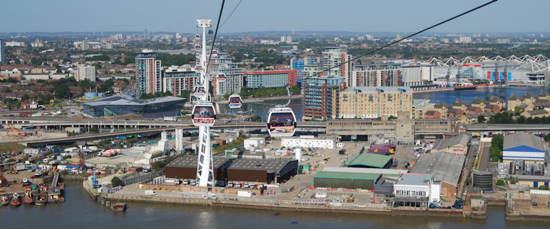
The Emirates Air Line is the UK's first urban cable car and the latest crossing of the River Thames in London. The 1.1km long crossing connects the Royal Greenwich peninsula to the Royal Victoria Dock and forms part of a long term regeneration plan for East London. The Design and Build contract was awarded by Transport for London to main contractor Mace. Structural design was shared between Buro Happold, who were responsible for the design of the three main towers, and URS, who designed the stations and adjacent compression towers. URS also carried out a Category 3 check of the design of the main towers using LUSAS Civil & Structural analysis software and LUSAS consultancy services to assist with this task.
Media
Overview
The height and positioning of the three main towers were dictated by a number of site constraints. The main South and North towers had to be tall enough to provide sufficient navigational clearance to the suspended gondolas for shipping. Ideally, the South Tower would have been positioned out of the river, but the development plot for the South Station was fixed, and very close to the river. This meant that the tower's positioning was governed by the steepest practical ascent rate for the system resulting in it being located in the river just outside of the shipping lane. The North Tower is land-based and sited to accommodate the curved route of a potential future tunnel across the river at the same location as the cable car. The height of the North Intermediate tower was restricted by it being on the flight path from London City airport and its longitudinal position was dictated by the presence of the existing Docklands light rail line and road network.
Main Towers
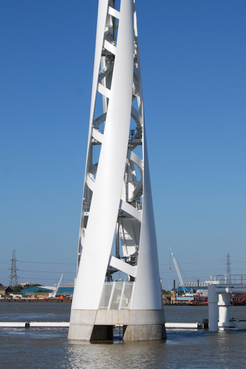
The 450 tonne South and North main towers each stand over 85m in height. They are formed from four, 40mm thick, steel plated ribbons that are doubly-curved and twist in an anti-clockwise direction as they rise in height. These ribbons, in turn, are stiffened internally by helical braces, formed from Circular Hollow Sections (CHS) faced with a steel plate, that twist in an opposing direction to the ribbons. Both towers taper from 10m diameter at their base, remain circular in cross-section until, at a height of around 53m, they become elliptical prior to being capped with a collar section. Then, they split and flare into two separate arms to carry the structural frame that supports the cable car yoke structure. In the narrow mid-section of each tower five torsion rings, fitted in addition to the helical steel, provide additional resistance to twisting forces. Two main ribbon to helix connection types are used in each tower. Near the base of the tower the length of the helix CHS that sits behind the ribbon is boxed out with steel plates. Further up the tower a large diameter CHS drum onto which the bracing members are fixed is used instead, with horizontal splice plates being used at any bolted joints. The smaller, 320 tonne, North Intermediate tower is similar in design to the taller main towers but has a 5.67m diameter footprint and stands just 60m in height. The towers were fabricated in segments then welded together to form larger sub-components that were lifted into position and bolted together.
Modelling methodology
As a consequence of their structural configuration the towers are flexible torsionally. They rely on the moment fixity of the ribbon and helix connections to restrict the rotational displacement of the top of each tower to the 0.003 radian rotation limit specified by Doppelmayr, the cable car installers. As part of its comprehensive overall design check, URS carried out a global analysis of the towers to check for compliance with overall deflection limits at the Serviceability Limit State. For the tower analysis a LUSAS geometry model was created via a tailored IGES import. It was not viable to use shell elements to represent all the structural components in the tower in detail, so the upper arms of the head, the ribbons and the helix connection stiffeners were modelled using thick shells, and thick beam elements represented the helix CHS and all other members. To ensure that the behaviour of the tower would be captured correctly when the ribbon and helix connections were modelled in this way detailed localised calibration studies were carried out for the two basic connection types used. James Rowe, Technical Director, URS said: "Results from connection models made exclusively from shell elements were compared to those from comparable nodes on the same connections modelled with shells and beams. This allowed the plate thicknesses for the joints on the global model to be artificially adjusted to ensure the connections on the global model were of the correct stiffness." He continues: "Ensuring that the LUSAS tower models correctly represented the ribbon to helix connections was a key step towards URS verifying the original structural design as part of the Category 3 check, and ultimately confirming its adequacy to EC3."
Modelling and analysis
Models of each tower were built in LUSAS and similar analyses and checks were carried out for each. In modelling the South Tower around 130 multi-varying cross-section properties needed to be defined and assigned to the model geometry. In addition to the connection sensitivity studies previously described, mesh sensitivity analyses for the whole tower derived an optimum number of beam and shell elements for the accuracy required and for the numerous analyses that needed to be carried out.
Eigenvalue frequency analyses took account of the stiffnesses of the substructures and included significant lumped masses (3 x 12.1 tonnes in the case of the South Tower) that represented the weight of cable car support systems applied to the support frame at the top of the towers. From these analyses it was seen that, for each tower, the first mode shape was orthogonal to the run of the cables, the second was generally an in-plane mode, and the third was a torsional mode. By performing a global linear buckling analysis on the tower for the most adverse design load combination it was found that a second order analysis was not required. However, a geometrically nonlinear analysis was also performed to confirm this and showed a minimal increase in deformations in comparison to the linear analysis undertaken.
Loading for the towers consisted of three main components: cable car loading to the top of each tower; direct wind loading on the tower surfaces and other wind induced loads (to BS EN 1991-1-4:2005 and NA); and temperature loading from direct sun irradiation (to BS EN 1991-1-5:2003). Wind loading actions were of particular interest and required wind tunnel testing and detailed analytical evaluation to assess potential flutter, vortex shedding, galloping and buffeting effects. Accidental loadings considered derailment of the cable cars; deropement of the cable; loss of support to a ribbon at base level, and fire - which involved checking the stress and buckling in the structure for localised reduced Young's modulus and Yield stress.
To assist with the ULS and SLS checks on the towers, numerous project-specific VB scripts were developed for use with LUSAS to allow for slicing through the model to create results for multiple loadcases; for enveloping shell stresses; and for the calculation of modal rotational inertia for torsional modes of vibration. The large number, variety and complex arrangement of the loadings meant that many combinations and design cases needed to be considered. VB scripting was employed here too, automating the creation of over 700 load combinations and envelopes. Use of the scripts in conjunction with other results from the vast range of LUSAS analyses undertaken allowed stresses in the ribbons, stiffeners, diaphragms and welds to be obtained and verified.
In summary
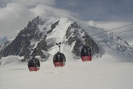
Emirates Air Line gets its name from the Emirates airline who substantially part-sponsored its construction. Its 34 gondolas have the capacity to carry up to 2,500 people per hour in each direction. It opened to the public in July 2012 after a rapid 15 month design and construction period.
Project team
| Main Contractor: | Mace |
| Architect: | Aedas Architects |
| Consulting Engineers: | Buro Happold / URS |
| Steelwork Fabricator: | Watson Steel Structures Ltd. |
| Piling/Foundations: | Soletanche Bachy |
| Cable car installation: | Doppelmayr |
"The use and assistance of LUSAS in conjunction with our own substantial in-house expertise allowed us to carry out a challenging Category 3 design check on a very unusual structure within a very tight timescale"
James Rowe, Technical Director, URS
References

Greenwich, London, England, United Kingdom, Europe - Newham, London, England, United Kingdom (2012)
Structure Types
- About this
data sheet - Product-ID
6143 - Published on:
11/02/2013 - Last updated on:
17/11/2021